In the ever-evolving landscape of networking technologies, the demand for flexibility, scalability, and cost-efficiency has driven the rise of disaggregated solutions. Network operators are increasingly embracing the disaggregated approach to leverage the advantages it offers. However, in order to seamlessly integrate disaggregated solutions with existing network infrastructures, interoperability becomes a paramount consideration. This is particularly crucial for ISPs and mobile operators heavily reliant on MPLS (Multiprotocol Label Switching) at both L3VPN and L2VPN levels. In this lab, we explore the interoperability between IP Infusion OcNOS and Cisco IOS XE used on many Cisco devices such as the ASR 900 series and ASR 1000 widely deployed in service provider networks.
Most mobile operators and internet service providers use MPLS in their core, aggregation and access networks with a mix of L3VPN and L2VPN to deliver a wide range of connectivity services to their customers, such as site-to-site connectivity, virtual private LAN services, and more. Hence, ensuring interoperability between disaggregated solutions like IP Infusion OcNOS and established platforms like Cisco becomes imperative for seamless service delivery, network scalability, and efficient resource allocation. With proven interoperability between disaggregated solutions and traditional solutions, service providers can leverage the strengths of both traditional and disaggregated solutions. They can maintain their existing Cisco-based MPLS infrastructure, benefitting from the reliability and extensive feature set. At the same time, they can introduce disaggregated solutions based on IP InfusionOcNOS to unlock cost efficiencies, customization options, and the ability to select best-of-breed hardware platforms. This interoperability empowers service providers to gradually migrate and evolve their networks, leveraging the advantages of disaggregated solutions without disrupting their established services or compromising on performance.
In this lab we explore the interoperability between OcNOS and IOS XE in a network based on OSPF, LDP, MP-BGP, L3VPN and L2VPN.
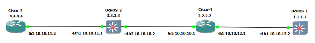
We are going to use the same topology and IP address configuration as our previous article: Configuring MPLS L3VPN on OcNOS but we will replace two OcNOS routers with the Cisco CSR1000v.
We start by configuring our interfaces.
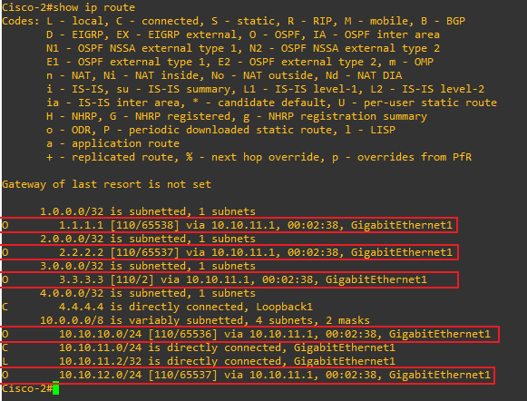
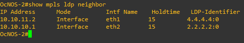
Then we configure OSPF as our IGP and advertise our networks.
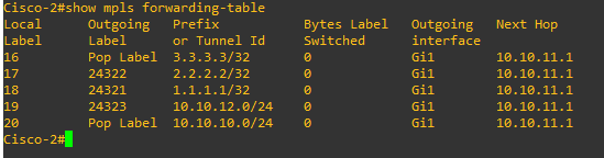
And voilà! With these steps we should have L3VPN successfully configured. But we will run few show commands to verify that things are working as expected.
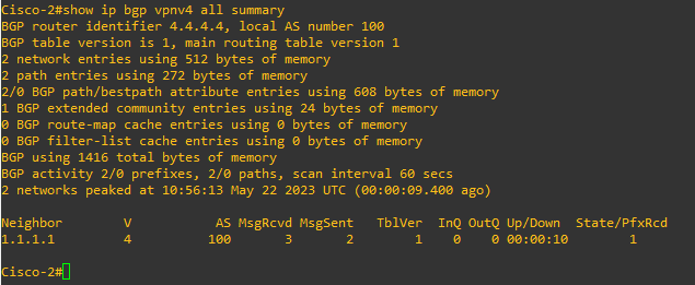
“show ip bgp vpnv4 all summary” command output shows us that BGP is established between the PE routers.
VRF instance “station1” routing table on the Cisco-2, we can see the route to subnet 20.0.0.0/24 learned via BGP.
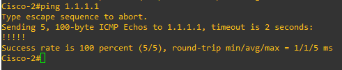
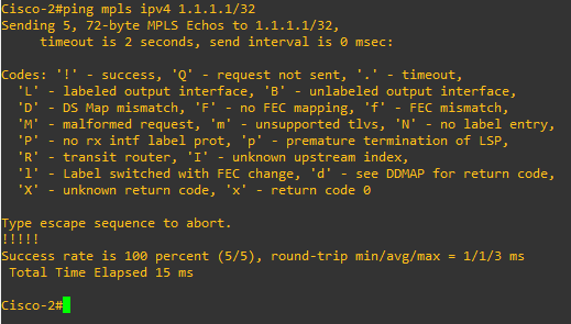
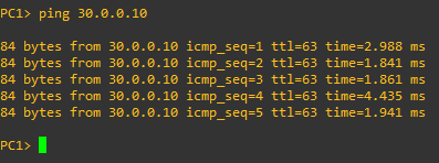
We now try pinging from PC1 to PC2.
The ping from PC1 to PC2 is successful confirming that ICMP packets are being routed in the L3VPN over the MPLS network.
L2VPN configuration
An MPLS Layer 2 VPN is a virtual private network service that enables the transparent extension of Layer 2 connectivity across multiple sites or customers, facilitating the seamless transmission of data as if all locations were part of the same local network.
The are two main types of L2VPN:
● Virtual Private Wire Service (VPWS)
● Virtual Private LAN Service (VPLS)
Virtual Private Wire Service or VPWS is a Point-to-Point (P2P) service implementation of L2VPN. It provides layer 2 data flow to the MPLS core attaching the two customer sites.
In this article we will configure a VPWS between the two PE routers to demonstrate its interoperability between OcNOS and Cisco IOS XE. We will demonstrate this capability on a real network with a Cisco ASR920 (loopack interface IP 10.128.0.142) and a UfiSpace S9500-22XST whitebox router running IP Infusion OcNOS (loopback interface IP 10.128.0.1).
The first step is configuring targeted LDP sessions between the two PE routers.
On the OcNOS Router
First step is to configure the targeted LDP session to the loopback of the remote PE
If everything is configured properly on the remote PE router, then the VPWS circuit should come up. To verify the status, we use the command below:
OcNOS#show ldp mpls-l2-circuit
Transport Client VC VC Local Remote Destination
VC ID Binding State Type VC Label VC Label Address
723 xe8 UP Ethernet VLAN 25731 108 10.128.0.142
We can see further details, using the word “detail”
MP-DCSG-HQ101# show mpls l2-circuit detail
MPLS Layer-2 Virtual Circuit: VPWS, id: 723 PW-INDEX: 4 service-tpid: dot1.q
Endpoint: 10.128.0.142
Control Word: 0
MPLS Layer-2 Virtual Circuit Group: none
Bound to interface: xe8
Virtual Circuit Type: Ethernet VLAN
Virtual Circuit is configured as Primary
Virtual Circuit is configured as Active
Virtual Circuit is active
Service-template : ISP_VPWS
Match criteria : 723
Cisco ASR 920 Configuration
The Cisco IOS XE configuration of the VPWS uses Ethernet Over MPLS as the transport mechanism. Under the interface where the CE connects, we configure a service instance and configure the encapsulation type to 802.1q. Then we bind the Ethernet port interface to the attachment circuit to create a pseudowire. We used virtual circuit (VC) 723 to uniquely identify the PW. We have to ensure that the remote PE router is configured with the same VC ID.
Cisco# configure terminal
Cisco(config)# interface GigabitEthernet0/0/7
Cisco(config-if)# no ip address
Cisco(config-if)# service instance 723 ethernet
Cisco(config-if-srv)# encapsulation dot1q 723
Cisco(config-if-srv)# xconnect 10.128.0.1 723 encapsulation mpls
Cisco(config-if-srv)# end
We verify that an LDP session is established between the two PE routers.
Cisco#show mpls l2transport vc 723
Local intf Local circuit Dest address VC ID Status
------------- -------------------------- --------------- ---------- ----------
Gi0/0/7 Eth VLAN 723 10.128.0.1 723 UP
To see further details
Cisco#show mpls l2transport vc 723 detail
Local interface: Gi0/0/7 up, line protocol up, Eth VLAN 723 up
Destination address: 10.128.0.1, VC ID: 723, VC status: up
Output interface: Te0/0/13, imposed label stack {25731}
Preferred path: not configured
Default path: active
Next hop: 10.128.2.37
Create time: 29w6d, last status change time: 2d14h
Last label FSM state change time: 2d14h
Last peer autosense occurred at: 2d14h
Signaling protocol: LDP, peer 10.128.0.1:0 up
Targeted Hello: 10.128.0.142(LDP Id) -> 10.128.0.1, LDP is UP
Graceful restart: not configured and not enabled
Non stop routing: not configured and not enabled
Status TLV support (local/remote) : enabled/not supported
LDP route watch : enabled
Label/status state machine : established, LruRru
Last local dataplane status rcvd: No fault
Last BFD dataplane status rcvd: Not sent
Last BFD peer monitor status rcvd: No fault
Last local AC circuit status rcvd: No fault
Last local AC circuit status sent: No fault
Last local PW i/f circ status rcvd: No fault
Last local LDP TLV status sent: No fault
Last remote LDP TLV status rcvd: Not sent
Last remote LDP ADJ status rcvd: No fault
MPLS VC labels: local 108, remote 25731
Group ID: local 13, remote 0
MTU: local 1500, remote 1500
Remote interface description:
Sequencing: receive disabled, send disabled
Control Word: Off (configured: autosense)
SSO Descriptor: 10.128.0.1/723, local label: 108
Dataplane:
SSM segment/switch IDs: 25387/4139 (used), PWID: 2
VC statistics:
transit packet totals: receive 1705345055, send 1131454978
transit byte totals: receive 2084759586119, send 295612374235
transit packet drops: receive 0, seq error 0, send 0
MPLS L3VPN and L2VPN services are widely used in many service provider networks to deliver services to multiple end-customers over the same network infrastructure. This lab demonstrated the interoperability between the Cisco IOS XE widely used in service providers’ networks and the IP Infusion OcNOS which is growing in popularity in service providers’ networks due to its flexibility, its advanced features and cost-effectiveness.
In future labs and articles, we will test the interoperability of additional protocols between the OcNOS and Cisco such as Segment Routing, EVPN, etc.