Configuring MPLS L3VPN on IP Infusion OcNOS

Configuration of MPLS L3VPN on IP Infusion OcNOS

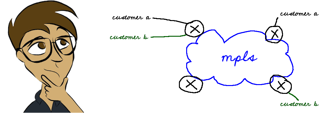
In this hands-on article, we will have a look at MPLS L3VPN configuration on the IP Infusion OcNOS Network Operating System.

Multiprotocol Label Switching (MPLS) has become a fundamental technology for modern networks, used by a wide range of organizations including Internet Service Providers, mobile operators and large enterprises. The main benefit of MPLS is its ability to provide fast and efficient packet forwarding with minimal overhead. By assigning labels to packets, MPLS allows routers to forward packets based on labels rather than having to perform time consuming IP lookups for each packet. This results in faster and more efficient packet forwarding and improved network performance.

Label assignment is an essential element of MPLS networks and there are several protocols available for label distribution in MPLS networks. These include:

  1. LDP (Label Distribution Protocol): LDP is the most widely used protocol for label distribution in MPLS networks. It is a simple and efficient protocol that uses TCP/IP to exchange label information between routers.

  2. RSVP-TE (Resource Reservation Protocol – Traffic Engineering): RSVP-TE is a more complex protocol than LDP and is typically used for MPLS traffic engineering. RSVP-TE uses a signaling process to establish Label Switched Paths (LSPs) through the network and to reserve bandwidth along those paths.

  3. BGP (Border Gateway Protocol): BGP is primarily used for Internet routing, but it can also be used for label distribution in MPLS networks.

  4. SR (Segment Routing): SR is a newer protocol for MPLS label distribution that is gaining popularity. It simplifies the MPLS network by using a source-routing paradigm, where the source node specifies the path through the network by including the labels of the intermediate nodes in the packet header.

Each protocol has its own strengths and weaknesses, and the choice of which protocol to use depends on the specific requirements of the network. LDP is the most widely used protocol for label distribution, but RSVP-TE is often used for MPLS traffic engineering. BGP and SR are also gaining in popularity for specific use cases.

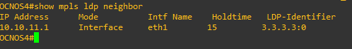
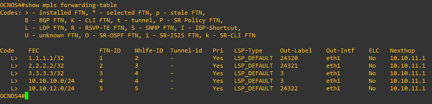
In this example we will use LDP which is scalable and easy to configure.

LDP works with an IGP such as OSPF or IS-IS to create label-switched paths (LSP) used when forwarding packets. LDP is responsible for assigning labels to the IP prefixes learned by the IGP, and for distributing those labels to the other routers in the network.


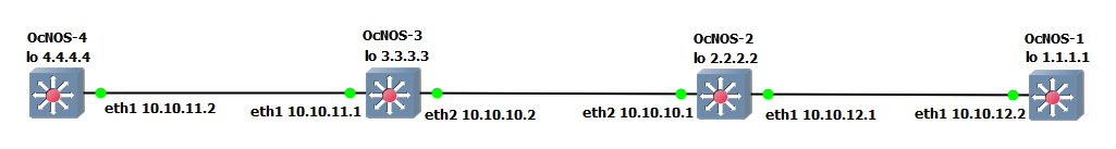
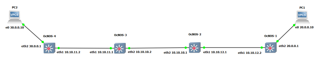
The first step is to configure the IGP, in this example we will use OSPF.

We start by assigning IP addresses to the routers Network to Network Interfaces (NNI). Then we enable OSPF on the routers (we will be using a single OSPF area).


Next, each router needs to inform other routers about its networks. To do this, the “network” command is used, along with the IP address and subnet mask of the network, as well as the OSPF area to which the network belongs.


Configuration on OcNOS_1:

OcNOS1(config)#router ospf 1
OcNOS1(config-router)#router-id 1.1.1.1
OcNOS1(config-router)#network 10.10.12.0/24 area 0
OcNOS1(config-router)#network 1.1.1.1/32 area 0
OcNOS1(config-router)#commit

Configuration on OcNOS_2:

OcNOS2(config)#router ospf 1
OcNOS2(config-router)#router-id 2.2.2.2
OcNOS2(config-router)#network 10.10.12.0/24 area
OcNOS2(config-router)#network 10.10.10.0/24 area 0
OcNOS2(config-router)#network 2.2.2.2/32 area 0
OcNOS2(config-router)#commit

Configuration on OcNOS_3:

OcNOS3(config)#router ospf 1
OcNOS3(config-router)#router-id 3.3.3.3
OcNOS3(config-router)#network 10.10.10.0/24 area 0
OcNOS3(config-router)#network 10.10.11.0/24 area 0
OcNOS3(config-router)#network 3.3.3.3/32 area 0
OcNOS3(config-router)#commit

Configuration on OcNOS_4:

OcNOS4(config)#router ospf 1
OcNOS4(config-router)#router-id 4.4.4.4
OcNOS4(config-router)#network 10.10.11.0/24 area 0
OcNOS4(config-router)#network 4.4.4.4/32 area 0
OcNOS4(config-router)#commit

We quickly verify OSPF is configured properly

The output of the “show ip ospf neighbor” on OCNOS_1 shows us that it has established an OSPF adjacency with OCNOS_2.

The “show ip route” shows us that the router is learning routes to the loopback IP addresses of the other routers in the topology via OSPF.

Now we have a working environment, and the routers can ping each other

Successful ping from OcNOS_4 to OcNOS_1


Now that OSPF is running properly, it’s time to move on to the next piece of the puzzle and explore the MPLS LDP configuration.

To configure LDP, we first need to enable LDP on the router, configure the router ID, configure the LDP transport address and enable label switching on our NNI interfaces.

It is common practice to use a loopback interface as the router ID. The transport address is the IP address used for creating the TCP session between neighboring routers. It is important that the transport-address is reachable by other routers.


Configuration on OcNOS_1:

OcNOS1(config)#router ldp
OcNOS1(config-router)#router-id 1.1.1.1
OcNOS1(config-router)#transport-address ipv4 1.1.1.1
OcNOS1(config-router)#exit

OcNOS1(config)#interface eth1
OcNOS1(config-if)#label-switching
OcNOS1(config-if)#enable-ldp ipv4
OcNOS1(config-if)#commit

Configuration on OcNOS_2:

OcNOS2(config)#router ldp
OcNOS2(config-router)#router-id 2.2.2.2
OcNOS2(config-router)#transport-address ipv4 2.2.2.2
OcNOS2(config-router)#exit

OcNOS2(config)#interface eth1
OcNOS2(config-if)#label-switching
OcNOS2(config-if)#enable-ldp ipv4
OcNOS2(config-if)#exit

OcNOS2(config)#interface eth2
OcNOS2(config-if)#label-switching
OcNOS2(config-if)#enable-ldp ipv4
OcNOS2(config-if)#commit

Configuration on OcNOS_3:

OcNOS3(config)#router ldp
OcNOS3(config-router)#router-id 3.3.3.3
OcNOS3(config-router)#transport-address ipv4 3.3.3.3
OcNOS3(config-router)#exit

OcNOS3(config)#interface eth1
OcNOS3(config-if)#label-switching
OcNOS3(config-if)#enable-ldp ipv4
OcNOS3(config-if)#exit

OcNOS3(config)#interface eth2
OcNOS3(config-if)#label-switching
OcNOS3(config-if)#enable-ldp ipv4
OcNOS3(config-if)#commit

Configuration on OcNOS_4:

OcNOS4(config)#router ldp
OcNOS4(config-router)#router-id 4.4.4.4
OcNOS4(config-router)#transport-address ipv4 4.4.4.4
OcNOS4(config-router)#exit

OcNOS4(config)#interface eth1
OcNOS4(config-if)#label-switching
OcNOS4(config-if)#enable-ldp ipv4
OcNOS4(config-if)#commit

Explanation:

router ldp – Enable LDP on the router.

Router-id – configures the IP address to be used as the LDP router-id. We have used the loopback IP as router-id.

transport-address ipv4 [IP address] – Configure the transport address to be used for a TCP session over which LDP will run on an IPV4 interface. Note: It is preferable to use the loopback address as transport address.

Under the interfaces:

label-switching – Enable label switching on the interface.

enable-ldp ipv4 – Enable LDP on the interface.


We can verify LDP configuration by using the following commands:

show mpls ldp neighbor – Displays the list of LDP neighbors that the router has established adjacency with.

show mpls forwarding-table display the MPLS forwarding table. It shows the mapping between MPLS labels and network prefixes, as well as the outgoing label and interface and the next hop.

ping mpls ldp –  Command used to verify LDP neighbor reachability and confirm MPLS label exchange functionality.

With MPLS LDP setup complete, we’re ready to start the L3VPN configuration.


L3VPN (Layer 3 Virtual Private Network) is a technology that enables businesses to securely connect geographically dispersed sites over a shared IP infrastructure. L3VPN is typically used by enterprises with multiple locations, such as service providers, data centers, branch offices, and remote workers, to access corporate resources securely and efficiently.

L3VPN provides several benefits over traditional point-to-point connections:

●        It eliminates the need for dedicated circuits between sites, allowing for easier scalability and cost savings.

●        It also provides improved security and privacy by encapsulating traffic within a private tunnel, which is isolated from other customers on the shared infrastructure. This ensures that sensitive data remains confidential and secure.

Having discussed the benefits and use cases of L3VPN, let’s now dive into its configuration and implementation!

For the sake of this test:

OcNOS_1 and OcNOS_4 will act as the Provider Edge (PE) routers.

OcNOS_2 and OcNOS_3 will act as the Provider (P) routers.

PC1 and PC2 will act as the customer edge (CE).

We will add PC1 and PC2 to our topology, assign an IP address for the PCs as well as their default gateway.

First, we need to create the VRFs and associate interfaces to those VRFs.

A VRF (Virtual Routing and Forwarding) is a technique to create multiple instances of a routing table on a single router. Each VRF instance operates as if it is an independent router, with its own forwarding table, interfaces, and routing policies. This allows multiple virtual networks to be created and run over a single physical network infrastructure.

Each PE router in the MPLS-VPN backbone is attached to a site that receives routes from a specific VPN, so the PE router must have the relevant VRF configuration for that VPN.


Configuration on OcNOS_1:

OcNOS1(config)#ip vrf station1
OcNOS1(config-vrf)#rd 1.1.1.1:4
OcNOS1(config-vrf)#route-target both 100:4
OcNOS1(config-vrf)#exit

OcNOS1(config)#interface eth2
OcNOS1(config-if)#ip vrf forwarding station1
OcNOS1(config-if)#ip address 20.0.0.1/24
OcNOS1(config-if)#commit

Configuration on OcNOS_4:

OcNOS4(config)#ip vrf station1
OcNOS4(config-vrf)#rd 4.4.4.4:4
OcNOS4(config-vrf)#route-target both 100:4
OcNOS4(config-vrf)#exit

OcNOS4(config)#interface eth2
OcNOS4(config-if)#ip vrf forwarding station1
OcNOS4(config-if)#ip address 30.0.0.1/24
OcNOS4(config-if)#commit

Explanation:

ip vrf station1 – Create the vrf instance “station1”.

rd 1.1.1.1:4 – Assigns a unique identifier to a L3VPN route to avoid conflicts with other VPNs using the same IP address prefixes.

route-target-both 100:4 – Specifies that the VRF instance “station1” should both import and export VPN routes that have the route target extended community “100:4”.

ip vrf forwarding station1 – Is used under the interface configuration to attach interface eth2 to the VRF “station1”


Next, we need to configure BGP between the two PEs.

BGP enables the exchange of routing information between networks, allowing the PE routers to share information about customer routes and VPN labels. This information exchange is crucial for the proper routing of customer traffic across the VPN.


Configuration on OcNOS_1:

OcNOS1(config)#router bgp 100
OcNOS1(config-router)#neighbor 4.4.4.4 remote-as 100
OcNOS1(config-router)#neighbor 4.4.4.4 update-source 1.1.1.1

OcNOS1(config-router)#address-family vpnv4 unicast
OcNOS1(config-router-af)#neighbor 4.4.4.4 activate
OcNOS1(config-router-af)exit

OcNOS1(config-router)#address-family ipv4 vrf station1
OcNOS1(config-router-af)#redistribute connected
OcNOS1(config-router-af)#commit

Configuration on OcNOS_4:

OcNOS4(config)#router bgp 100
OcNOS4(config-router)#neighbor 1.1.1.1 remote-as 100
OcNOS4(config-router)#neighbor 1.1.1.1 update-source 4.4.4.4

OcNOS4(config-router)#address-family vpnv4 unicast
OcNOS4(config-router-af)#neighbor 1.1.1.1 activate
OcNOS4(config-router-af)exit

OcNOS4(config-router)#address-family ipv4 vrf station1
OcNOS4(config-router-af)#redistribute connected
OcNOS4(config-router-af)#commit

Explanation:

router bgp 100 – Configures a BGP instance with an autonomous system number (ASN) of 100, enabling BGP routing.

neighbor 1.1.1.1 remote-as 100 – Establishes a BGP peering session between the local router and the remote BGP router (1.1.1.1) with an ASN of 100.

neighbor 1.1.1.1 update-source 4.4.4.4 – Specifies the source IP address for BGP updates sent to the neighbor.

address-family vpnv4 unicast – Activates the VPNv4 address family for BGP, allowing the exchange of routing information for L3VPN between BGP routers.

neighbor 1.1.1.1 activate – Activates the BGP neighbor for the VPNv4 address family.

address-family ipv4 vrf station1 – Activates the IPv4 address family for the VRF instance “station1”. It enables the exchange of IPv4 prefixes for the VRF, creating isolated L3VPNs.

redistribute-connected – Enables the advertisement of locally connected routes to other BGP routers that are part of the “station1” VRF instance.

That’s it, we successfully configured L3VPN!


 We can verify our L3VPN configuration by using the following commands:

show ip bgp vpnv4 all – Displays the BGP routing table for VPNv4 address family, which shows the learned VPNv4 routes and associated BGP next-hops.

show ip route vrf station1 – displays the routing table for the VRF instance “station1”.

Show mpls vrf-forwarding-table vrf station1 – display the MPLS VPN forwarding table for the VRF instance “station1”.

Successful ping from PC1 to PC2


I hope you enjoyed this article, and if you have any questions or comments, please don’t hesitate to leave them below.

1 comment on “Configuring MPLS L3VPN on IP Infusion OcNOS

Leave a Reply

Your email address will not be published. Required fields are marked *