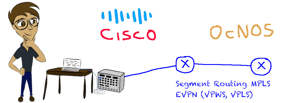
In our latest lab experiment, we investigate the interoperability between the IP Infusion OcNOS and Cisco IOS XR. In this exercise we test interoperability of the following protocols: ISIS, Segment Routing MPLS, MP-BGP, L3VPN, EVPN/VPWS, and EVPN/VPLS.
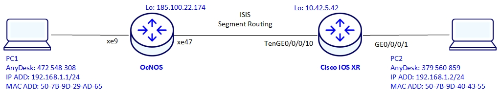
Below is an illustration of the lab setup used for testing:
We will first start by configuring the IGP, in this test, ISIS will be used with Segment Routing MPLS for label exchange.
Segment Routing MPLS is enabled under router IS-IS and a prefix-SID is configured under the loopback interface.
Note that MPLS forwarding is enabled on IS-IS interfaces.
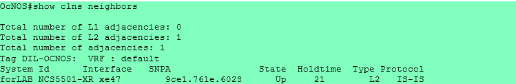
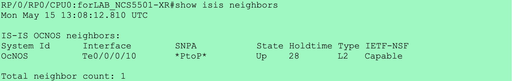
We can verify the ISIS adjacency by using the command show clns neighbors on the OcNOS
And as you can see, the state is up
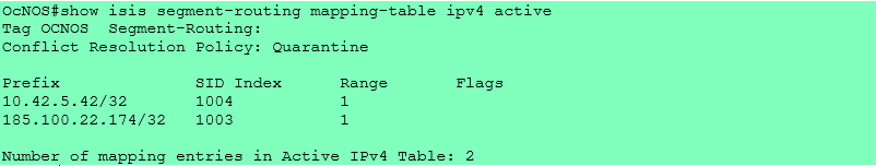
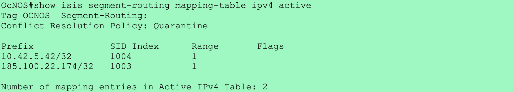
Now let’s take a look at the active IPV4 segment routing mappings
And here we see the MPLS forwarding table on the OcNOS.
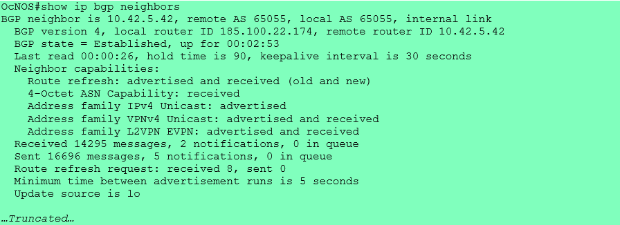
We also verify the same on the Cisco. Note that the commands are slightly different but very similar.
The state of the ISIS neighbor is UP meaning that adjacency was correctly established between the OcNOS and the Cisco IOS XR.
Here we see the label mapping information related to segment routing in the IS-IS protocol
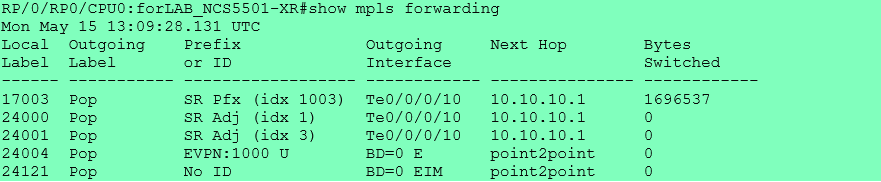
And here we see the MPLS forwarding table on Cisco.
Now let’s jump to MP-BGP configuration.
In our case we use 2 types of address families:
vpnv4, used to exchange routing information for IPv4 prefixes in the context of Virtual Private Networks (VPNs)
l2vpn evpn, used to exchange routing and reachability information for Layer 2 services, specifically Ethernet VPNs, in the context of Virtual Private Networks (VPNs).
The control-word is enabled by default on the Cisco IOS XR and disabled by default on the OcNOS. For the service to work both sides should match. Therefore we have disabled the control-word on the Cisco.
The other possibility could have been to enable the control-word on the OcNOS and leave it enabled on the Cisco. We tested this scenario separately and it worked.
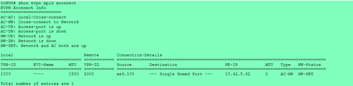
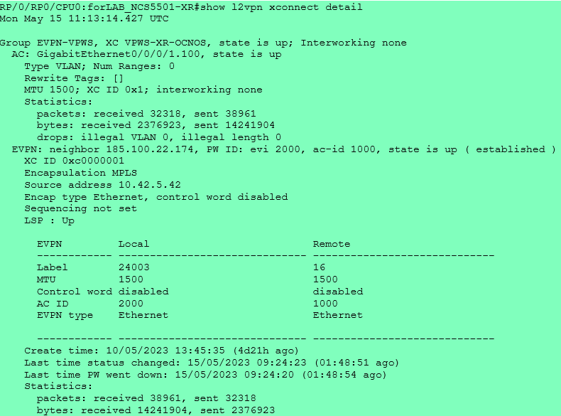
Let’s verify the state of the EVPN-VPWS on the OcNOS.
This shows us that that the Attachment Circuit and the network are UP. We can also see local EVPN ID, the remote ID, the attachment interface, and the IP of the remote PE.
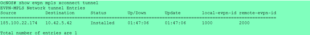
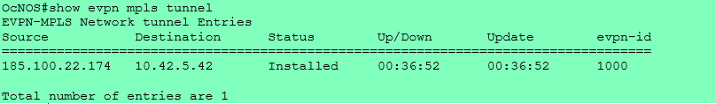
Here we see the satus of the tunnel, it is installed and how long it has been UP.
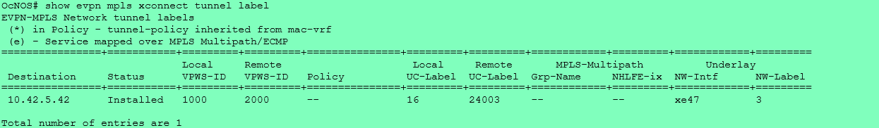
And we can also the tunnel labels.
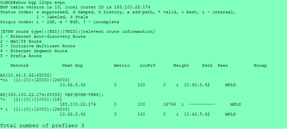
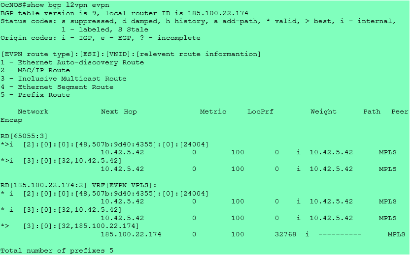
The “show bgp l2vpn evpn” command displays information about EVPN routes exchanged with the BGP peers, in this case with the Cisco.
We can see the Route distinguisher of the Cisco, we see the EVPN route type, in this case type 1 for Ethernet routes. We also see VNID, the label, the next hop, local preference and so on.
Now let’s verify the same on Cisco
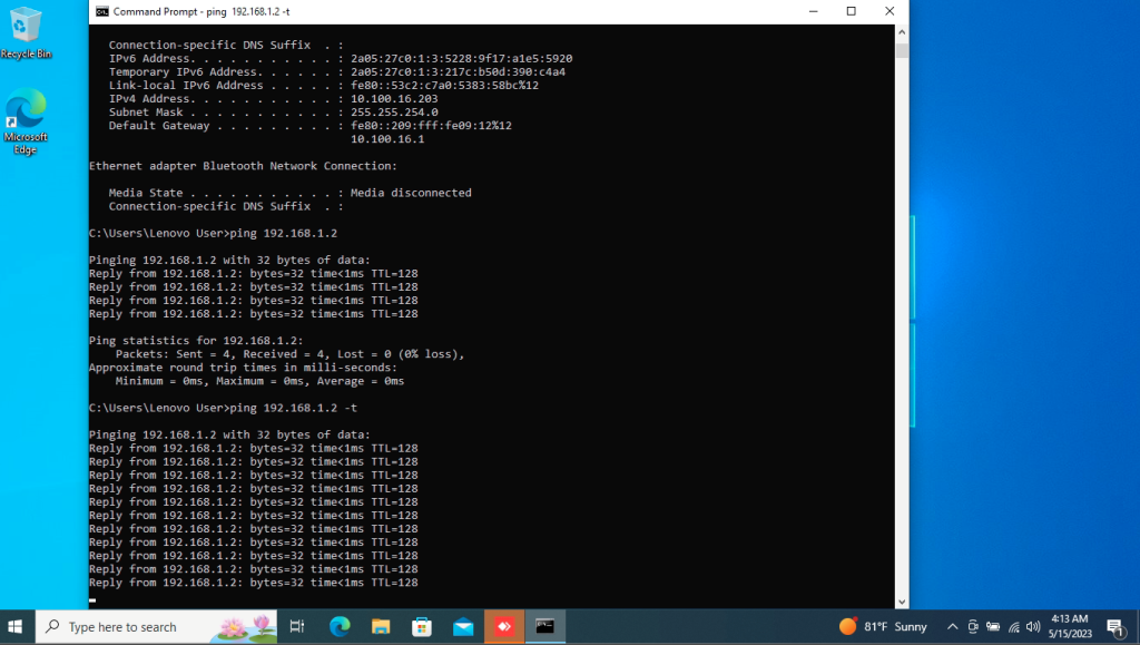
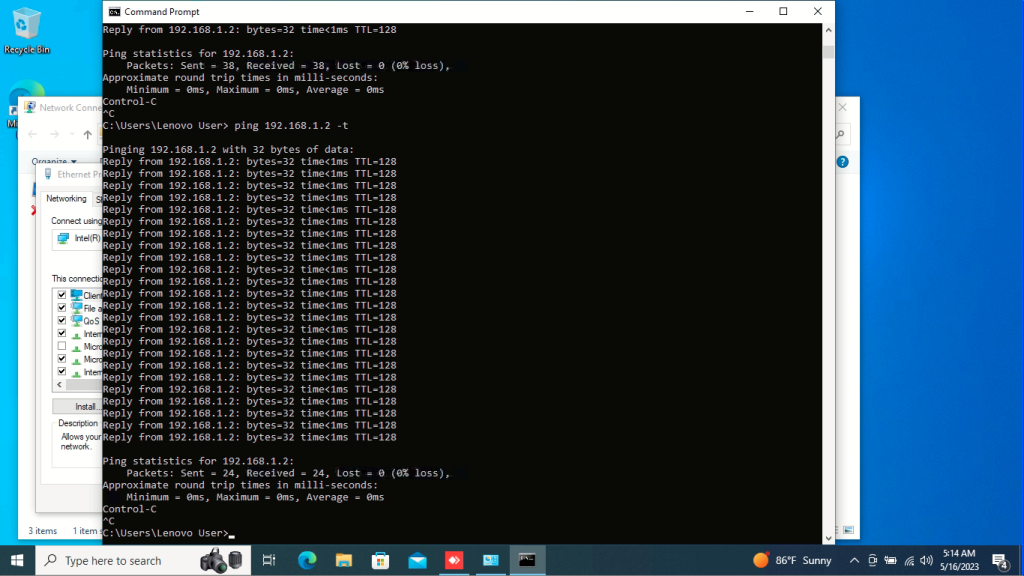
Now to verify that our EVPN-VPWS forwards traffic, we will do a ping test between the two PCs on each end.
PC1 IP address:168.1.1/24
PC1 MAC address: 50-7B-9D-29-AD-65
PC2 IP address:168.1.2/24
PC2 MAC address: 50-7B-9D-40-43-55
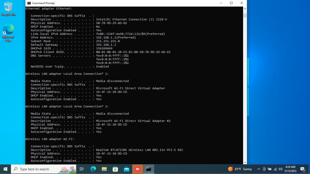
Figure 1: Interface configuration of PC1
Figure 2: Ping from PC1 to PC2
As you can see, we get a successful ping, the traffic is going through the EVPN-VPWS
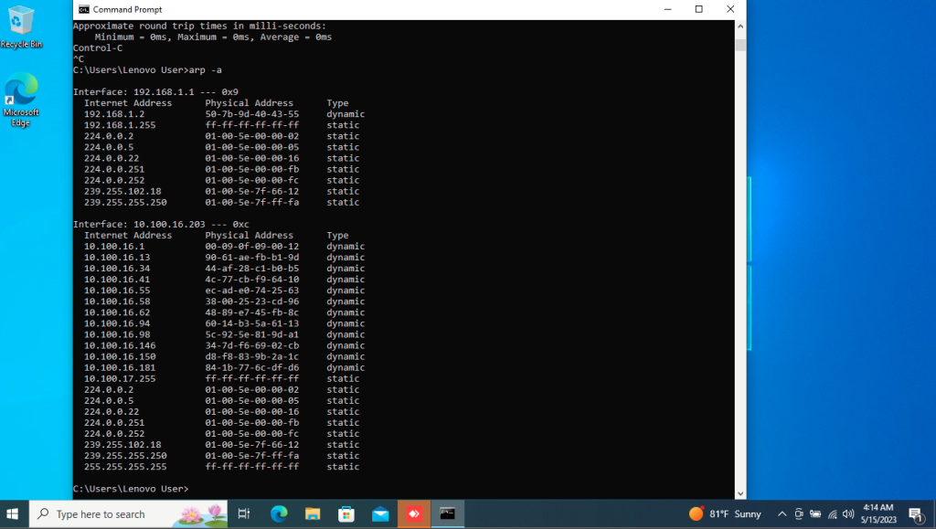
Figure 3: We verify the ARP table on PC1 and we can see the IP and MAC address of PC2
Additionally to EVPN-VPWS, we also tested EVPN-VPLS. We remove the VPWS configuration and replaced it with VPLS.