OcNOS EVPN-VXLAN IRB & BGP to Host
In this article we explore how to enable inter-subnet routing within a VXLAN overlay on OcNOS using an IRB (Integrated Routing and Bridging) interface and a dedicated L3VNI.
We then extend the design by establishing a BGP session between the leaf switch and the directly connected host, giving the host the ability to advertise its own prefixes into the VRF and receive learned routes back.
This article builds on the foundational EVPN-VXLAN concepts (VTEP configuration, underlay OSPF, BGP EVPN control plane).
Topology
Design Overview
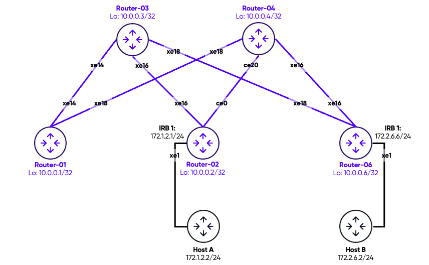
Our fabric is built around a classic spine-and-leaf topology.
- Two spine switches (Router-03and Router-04) act as BGP Route Reflectors for the EVPN address family.
- Two leaf switches (Router-02and Router-06) host the VTEP, IRB, and VRF configuration. A third switch, Router-01, participates in the underlay but carries no overlay configuration and is used to validate pure underlay reachability.
The design relies on a single tenant VRF (L3VRF1000) and one L2VNI (101000), with a single L3VNI (1000000) associated with the VRF.
Each leaf presents an IRB interface as the Layer-3 gateway for hosts in VNI 101000.
A BGP session is then established directly between the IRB interface and the host’s IP, redistributing connected and host routes into EVPN.
| Node | Loopback | Role | IRB / VRF |
| Router-01 | 10.0.0.1 | Leaf (underlay only) | — |
| Router-02 | 10.0.0.2 | Leaf VTEP | irb1 172.1.2.2/24 · L3VRF1000 |
| Router-03 | 10.0.0.3 | Spine / BGP RR | — |
| Router-04 | 10.0.0.4 | Spine / BGP RR | — |
| Router-06 | 10.0.0.6 | Leaf VTEP | irb1 172.2.6.6/24 · L3VRF1000 |
Configuration
Step 1: Underlay: OSPF and Loopbacks
Every router in the fabric uses OSPF area 0 to distribute loopback reachability. The loopback address (e.g. 10.0.0.2/32) is the VTEP source IP and the BGP update-source. The underlay point-to-point links connect leaves to both spines, giving two equal-cost paths for all VTEP-to-VTEP traffic.
Router-02 – Underlay
interface lo
 ip address 10.0.0.2/32 secondary
!
interface xe16
 ip address 10.2.4.2/24   # link to Router-04 (spine)
!
interface ce0
 ip address 10.2.3.2/24   # link to Router-03 (spine)
!
router ospf 1
 ospf router-id 10.0.0.2
 passive-interface lo enable
 network 10.0.0.2/32 area 0.0.0.0
 network 10.2.3.0/24 area 0.0.0.0
 network 10.2.4.0/24 area 0.0.0.0
Passive loopback: The passive-interface lo enable command prevents OSPF hellos from being sent on the loopback, which would be pointless, while still advertising the /32 into the OSPF domain. This is the standard pattern across all nodes.
Step 2: BGP Route Reflectors (Spines)
Both spine switches serve as iBGP Route Reflectors for the l2vpn evpn address family. They do not participate in the VXLAN overlay themselves — they simply reflect EVPN NLRI between all leaf clients. Each leaf peers with both spines for redundancy.
Router-03 – Route Reflector
router bgp 1
 bgp router-id 10.0.0.3
 no bgp inbound-route-filter
 neighbor 10.0.0.1 remote-as 1
 neighbor 10.0.0.1 update-source lo
 neighbor 10.0.0.2 remote-as 1
 neighbor 10.0.0.2 update-source lo
 neighbor 10.0.0.6 remote-as 1
 neighbor 10.0.0.6 update-source lo
 !
 address-family l2vpn evpn
 neighbor 10.0.0.1 activate
 neighbor 10.0.0.1 route-reflector-client
 neighbor 10.0.0.2 activate
 neighbor 10.0.0.2 route-reflector-client
 neighbor 10.0.0.6 activate
 neighbor 10.0.0.6 route-reflector-client
 exit-address-family
Router-04 mirrors this configuration exactly, peering with the same set of leaf loopbacks. Note the absence of any l3vpn or ipv4 vrf address family on the spines — the VRF routing is entirely local to the leaves and exchanged via the l2vpn evpn address family.
Step 3: VXLAN Global Mode and VTEP
On each leaf switch that participates in the overlay, three global statements activate the data-plane and control-plane features required for IRB:
Router-02 – VXLAN global
nvo vxlan enable                   # activate the VXLAN data plane
nvo vxlan irb                      # enable IRB mode (bridges L2 into L3 VRF)
evpn vxlan multihoming enable

nvo vxlan vtep-ip-global 10.0.0.2  # VTEP source = loopback
IRB mode must be enabled globally. The nvo vxlan irb command is mandatory before any irb interface can be associated with a VNI. Without it the IRB interface will be created but will not forward traffic between the L2 bridge domain and the L3 VRF.The relevant hardware profiles are also required for IRB and VXLAN filtering to function correctly.
Router-02 – Hardware profiles
hardware-profile filter egress-ipv4 enable
hardware-profile filter vxlan enable
hardware-profile filter vxlan-mh enable
hardware-profile statistics ac-lif enable
Step 4: VRF, MAC VRF, and L3VNI
OcNOS separates the Layer-2 broadcast domain from the Layer-3 routing domain using two distinct VRF constructs: a mac vrf for the L2VNI (the bridge domain) and an ip vrf for the L3VNI (the tenant routing table). Both must be configured on every leaf that participates in the tenant.
Router-02 – VRF definitions
! Layer-2 bridge domain
mac vrf L2VRF1
 rd 10.0.0.2:1
 route-target both 1:1

! Layer-3 tenant routing table
ip vrf L3VRF1000
 rd 10.0.0.2:1000
 route-target both 1:1
 l3vni 1000000
The VNI itself is then instantiated and linked to the L2VRF and IRB interface:
Router-02 – VNI 101000
nvo vxlan id 101000 ingress-replication
 vxlan host-reachability-protocol evpn-bgp L2VRF1
 evpn irb1                                       # attach the IRB interface to this VNI
 vni-name VNI_101000
Step 5: IRB interface
The IRB interface (Integrated Routing and Bridging) is the OcNOS equivalent of an SVI or BVI. It sits at the boundary between the L2 bridge domain (VNI 101000) and the L3 routing domain (L3VRF1000). Each leaf assigns a unique IP address to its IRB — unlike an anycast gateway where all leaves share the same IP.
Router-02 – IRB interface
interface irb1
 ip vrf forwarding L3VRF1000
 ip address 172.1.2.2/24
Router-06 – IRB interface
interface irb1
 ip vrf forwarding L3VRF1000
 ip address 172.2.6.6/24
Note that the two leaves use addresses in different subnets on their IRB interfaces (172.1.2.0/24 on Router-02, 172.2.6.0/24 on Router-06). Reachability between those subnets is achieved through the L3VNI: each leaf redistributes its connected IRB subnet into EVPN as a Type-5 prefix, which the other leaf imports into its VRF routing table.
Step 6: Access Port and Sub-interface Mapping
The host-facing port is configured as a switchport with a dot1q sub-interface that maps VLAN 1000 to VNI 101000. The rewrite pop strips the 802.1Q tag before the frame enters the bridge domain, and the access-if-evpn / map vpn-id binds the sub-interface to the VNI.
Router-02 – xe1 and sub-interface
interface xe1
 speed 1g
 switchport
 load-interval 30

interface xe1.1000 switchport
 encapsulation dot1q 1000
 rewrite pop
 load-interval 30
 access-if-evpn
  map vpn-id 101000              # bind to VNI 101000
Router-06 uses an identical configuration on its own
Router-06 uses an identical configuration on its own xe1.1000 sub-interface. The host connected to either leaf must tag its traffic with VLAN 1000, which is then stripped and placed into the L2VRF1 bridge domain by OcNOS.
Step 7: BGP Between Leaf and Host
Rather than relying on static routes or a shared anycast gateway, this design establishes a BGP session directly between the leaf’s IRB interface and the host. Both are in the same iBGP AS (AS 1). The leaf activates the session within the ipv4 vrf L3VRF1000 address family and redistributes both connected and host routes into EVPN.
Router-02 – BGP VRF address-family
router bgp 1
 ! ... EVPN peers with spines omitted for brevity ...
 !
 address-family ipv4 vrf L3VRF1000
 redistribute connected
  redistribute connected-host-routes
 neighbor 172.1.2.1 remote-as 1             # host IP
 neighbor 172.1.2.1 activate
 exit-address-family
Router-06 – BGP VRF address-family
router bgp 1
 !
 address-family ipv4 vrf L3VRF1000
 redistribute connected
 redistribute connected-host-routes
 neighbor 172.2.6.2 remote-as 1     ! host IP
 neighbor 172.2.6.2 activate
 exit-address-family
Why BGP to the host? When a host can run a routing daemon (e.g. FRR, BIRD, or a modern NOS), peering via BGP gives both sides full prefix visibility. The leaf learns the host’s specific /32 (or any prefix the host advertises) and injects it as an EVPN Type-5 route across the L3VNI, so any remote leaf can reach that host without relying on ARP/proxy-ARP. The host in turn receives the full VRF routing table from the leaf — including remote subnets learned over the L3VNI.
The redistribute connected-host-routes statement specifically redistributes /32 host routes from the VRF into BGP in addition to the broader redistribute connected for subnet prefixes. This ensures that individual host addresses are exported as EVPN Type-5 routes and visible to all remote VTEPs.
Step 8: Leaf EVPN Peers (Spines as RR Clients)
Each leaf peers with both spines for the l2vpn evpnrouter bgp 1
bgp router-id 10.0.0.2
neighbor 10.0.0.3 remote-as 1
neighbor 10.0.0.3 update-source lo
neighbor 10.0.0.3 advertisement-interval 0
neighbor 10.0.0.4 remote-as 1
neighbor 10.0.0.4 update-source lo
neighbor 10.0.0.4 advertisement-interval 0
!
address-family l2vpn evpn
neighbor 10.0.0.3 activate
neighbor 10.0.0.4 activate
exit-address-family
Router-06 – BGP VRF address-family
router bgp 1
 !
 address-family ipv4 vrf L3VRF1000
 redistribute connected
 redistribute connected-host-routes
 neighbor 172.2.6.2 remote-as 1     ! host IP
 neighbor 172.2.6.2 activate
 exit-address-family
The radvertisement-interval 0 removes any hold-down on EVPN updates, which is generally desirable in a data-centre fabric where fast convergence is a priority.
How It All Fits Together
When Host-A (172.1.2.1) on Router-02 wants to reach Host-B (172.2.6.2) on Router-06, the forwarding chain is as follows:
- Host-A sends a packet tagged VLAN 1000 toward Router-02 xe1. The dot1q sub-interface strips the tag and places the frame in the VNI 101000 bridge domain.
- The destination IP (172.2.6.2) is not in the local bridge domain. The IRB interface on Router-02 performs a Layer-3 lookup in L3VRF1000. It finds a Type-5 EVPN route for 172.2.6.2/32 (or 172.2.6.0/24) with a next-hop of 10.0.0.6.
- Router-02 encapsulates the IP packet in a VXLAN header using L3VNI 1000000 and forwards it across the underlay toward Router-06 (10.0.0.6).
- Router-06 decapsulates the VXLAN packet, looks up 172.2.6.2 in L3VRF1000, and delivers it to Host-B via the xe1 access port tagged with VLAN 1000.
L3VNI carries routed traffic. The key distinction here is that inter-subnet traffic uses the L3VNI (1000000), not the L2VNI (101000). The L2VNI is used only for intra-subnet bridged traffic between hosts that share the same /24. When the IRB routes a packet to a remote subnet, the L3VNI encapsulation is applied so that the far-end VTEP knows to deliver it into the VRF rather than the bridge domain.
Summary
This configuration demonstrates a complete OcNOS EVPN-VXLAN overlay with IRB-based distributed routing and BGP sessions to the host. The key components and their relationships are:
|
Component |
OcNOS construct |
Purpose |
|
L2 bridge domain |
mac vrf L2VRF1 |
Controls L2 EVPN route-target import/export for the VNI |
|
L3 tenant routing |
ip vrf L3VRF1000 |
Holds the per-tenant IP routing table; carries L3VNI |
|
Data-plane VNI |
nvo vxlan id 101000 |
Encapsulates tenant L2 frames; linked to L2VRF and IRB |
|
L3VNI |
l3vni 1000000 in ip vrf |
Encapsulates routed inter-subnet traffic between VTEPs |
|
IRB interface |
interface irb1 |
L3 gateway on the leaf; bridges VNI to the VRF |
|
Access port |
xe1.1000 / map vpn-id |
Maps host-facing 802.1Q frames into the VNI |
|
BGP to host |
neighbor 172.x.x.x in ipv4 vrf |
Exchanges host/prefix routes between leaf and host |
|
EVPN control plane |
l2vpn evpn AF |
Distributes Type-2 MAC/IP and Type-5 prefix routes via RR |
This article is part of the Pine Networks OcNOS Configuration series. All configurations were validated on OcNOS-CSR 7.0.0.262. Lab hardware includes Edgecore AS7316-26XB and UfiSpace S9500-22XST platforms.