SONiC Multi-Site DCI
This article describes a multi-site EVPN-VXLAN architecture using Enterprise SONiC, used interconnecting two independent data centers using eBGP EVPN over IP transport.
Each data center operates as an autonomous EVPN domain and is interconnected through border leaf VTEPs, which perform route re-origination, VXLAN decapsulation/encapsulation, and EVPN control-plane filtering.
We will cover:
- EVPN-VXLAN multi-site architecture overview
- Configuring the underlay network
- Configuring the overlay (EVPN)
- Configuring border leafs (multi-site DCI)
- VXLAN VTEP configuration (internal vs external)
- VLAN to VNI mapping
- Verification and validation
Topology
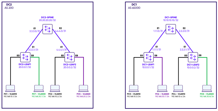
In a multi-site design, multiple EVPN fabrics (data centers) are interconnected using eBGP EVPN, where:
- Each DC is its own EVPN domain (separate ASN)
- Border VTEPs act as gateways between sites
- VXLAN tunnels are terminated and re-originated at the border VTEPs
This enables:
- Layer 2 extension across DCs
- Workload mobility between sites
- Scalable multi-domain EVPN fabrics
Configuration of the underlay and overlay for each Datacenter
Step 1: Interfaces Configuration and OSPF underlay
The first step is to configure Loopbacks and point-to-point links between Leaf and Spine switches. Then configure OSPF to create reachability between loopbacks within each datacenter.
Data Center 1
DC1-SPINE
router ospf
 ospf router-id 10.10.10.10
 area 0.0.0.0
!

interface Loopback 0
 ip address 10.10.10.10/32
 ip ospf area 0.0.0.0
!

interface Ethernet1
 no shutdown
 ip address 1.1.1.0/31
 ip ospf area 0.0.0.0
 ip ospf network point-to-point
!
interface Ethernet2
 no shutdown
 ip address 2.2.2.0/31
 ip ospf area 0.0.0.0
 ip ospf network point-to-point
!
DC1-LEAF1
router ospf
 ospf router-id 10.0.0.1
 area 0.0.0.0
!

interface Loopback 0
 ip address 10.0.0.1/32
 ip ospf area 0.0.0.0
!

interface Ethernet2
 no shutdown
 ip address 1.1.1.1/31
 ip ospf area 0.0.0.0
 ip ospf network point-to-point
!
DC1-LEAF2
router ospf
 ospf router-id 10.0.0.2
 area 0.0.0.0
!

interface Loopback 0
 ip address 10.0.0.2/32
 ip ospf area 0.0.0.0
!

interface Ethernet2
 no shutdown
 ip address 2.2.2.1/31
 ip ospf area 0.0.0.0
 ip ospf network point-to-point
!
Data Center 2
DC2-SPINE
router ospf
 ospf router-id 20.20.20.20
 area 0.0.0.0
!

interface Loopback 0
 ip address 20.20.20.20/32
 ip ospf area 0.0.0.0
!

interface Ethernet1
 no shutdown
 ip address 3.3.3.0/31
 ip ospf area 0.0.0.0
 ip ospf network point-to-point
!
interface Ethernet2
 no shutdown
 ip address 4.4.4.0/31
 ip ospf area 0.0.0.0
 ip ospf network point-to-point
!
DC2-LEAF1
router ospf
 ospf router-id 20.0.0.1
 area 0.0.0.0
!

interface Loopback 0
 ip address 20.0.0.1/32
 ip ospf area 0.0.0.0
!

interface Ethernet1
 no shutdown
 ip address 3.3.3.1/31
 ip ospf area 0.0.0.0
 ip ospf network point-to-point
!
DC2-LEAF2
router ospf
 ospf router-id 20.0.0.2
 area 0.0.0.0
!

interface Loopback 0
 ip address 20.0.0.2/32
 ip ospf area 0.0.0.0
!

interface Ethernet1
 no shutdown
 ip address 4.4.4.1/31
 ip ospf area 0.0.0.0
 ip ospf network point-to-point
!
Step 2: BGP
In this setup we use iBGP within each datacenter. Each Spine will be configured as route-reflector for the two leaves directly attached to it within the same datacenter.
Data Center 1
DC1-SPINE
router bgp 65000
 router-id 10.10.10.10
 log-neighbor-changes
!

 address-family l2vpn evpn
  advertise-all-vni
 !

 neighbor 10.0.0.1
  remote-as 65000
  update-source interface Loopback 0
  !
  address-family l2vpn evpn
   activate
   route-reflector-client
 !

 neighbor 10.0.0.2
  remote-as 65000
  update-source interface Loopback 0
  !
  address-family l2vpn evpn
   activate
   route-reflector-client
  !
DC1-LEAF1
router bgp 65000
 router-id 10.0.0.1
 log-neighbor-changes
 !

 address-family l2vpn evpn
  advertise-all-vni
!

 neighbor 10.10.10.10
  remote-as 65000
  !
  address-family l2vpn evpn
   activate
 !
DC1-LEAF2
router bgp 65000
 router-id 10.0.0.2
 log-neighbor-changes
 !

 address-family l2vpn evpn
  advertise-all-vni
 !

 neighbor 10.10.10.10
  remote-as 65000
  !
  address-family l2vpn evpn
   activate
!
Data Center 2
DC2-SPINE
router bgp 200
 router-id 20.20.20.20
 log-neighbor-changes
 !

 address-family l2vpn evpn
  advertise-all-vni
!

 neighbor 20.0.0.1
  remote-as 200
  update-source interface Loopback 0
  !
  address-family l2vpn evpn
   activate
   route-reflector-client
 !

 neighbor 20.0.0.2
  remote-as 200
  update-source interface Loopback 0
  !
  address-family l2vpn evpn
   activate
   route-reflector-client
!
DC2-LEAF1
router bgp 200
 router-id 20.0.0.1
 log-neighbor-changes
 !

 address-family l2vpn evpn
  advertise-all-vni
 !

 neighbor 20.20.20.20
  remote-as 200
  update-source interface Loopback 0
  !
  address-family l2vpn evpn
   activate
!
DC2-LEAF2
router bgp 200
 router-id 20.0.0.2
 log-neighbor-changes
 !

 address-family l2vpn evpn
  advertise-all-vni
!

 neighbor 20.20.20.20
  remote-as 200
  update-source interface Loopback 0
  !
  address-family l2vpn evpn
   activate
!
Step 3: Access interfaces
Data Center 1
DC1-LEAF1
interface Ethernet0
 no shutdown
 switchport access Vlan 10
!

interface Ethernet8
 no shutdown
 switchport access Vlan 20
DC1-LEAF2
interface Ethernet0
 no shutdown
 switchport access Vlan 10
!

interface Ethernet8
 no shutdown
 switchport access Vlan 30
Data Center 2
DC2-LEAF1
interface Ethernet0
 no shutdown
 switchport access Vlan 10
!
interface Ethernet8
 no shutdown
 switchport access Vlan 30
DC2-LEAF2
interface Ethernet0
 no shutdown
 switchport access Vlan 10
!
interface Ethernet8
 no shutdown
 switchport access Vlan 20
Step 4: VTEP and VLAN-VNI Mapping
Data Center 1
DC1-LEAF1
interface vxlan vtep1
 source-ip 10.0.0.1
 map vni 100010 vlan 10
 map vni 100020 vlan 20
DC1-LEAF2
interface vxlan vtep2
 source-ip 10.0.0.2
 map vni 100010 vlan 10
 map vni 100030 vlan 30
Data Center 2
DC2-LEAF1
interface vxlan vtep1
 source-ip 20.0.0.1
 map vni 100010 vlan 10
 map vni 100030 vlan 30
DC2-LEAF2
interface vxlan vtep2
 source-ip 20.0.0.2
 map vni 100010 vlan 10
 map vni 100020 vlan 20
Step 5: Verification of the overlay within each Data Center
DC1-LEAF1
DC1-LEAF1# show vxlan tunnel

        Name                SIP                DIP           source    Group     D-VNI     operstatus
        ====                ===                ===           ======    =====     =====     ==========
   EVPN_10.0.0.2          10.0.0.1           10.0.0.2         EVPN    internal     no       oper_up
DC1-LEAF2
DC1-LEAF2# show vxlan tunnel

        Name                SIP                DIP           source    Group     D-VNI     operstatus
        ====                ===                ===           ======    =====     =====     ==========
   EVPN_10.0.0.1          10.0.0.2           10.0.0.1         EVPN    internal     no       oper_up
DC2-LEAF1
DC2-LEAF1# show vxlan tunnel

        Name                SIP                DIP           source    Group     D-VNI     operstatus
        ====                ===                ===           ======    =====     =====     ==========
   EVPN_20.0.0.2          20.0.0.1           20.0.0.2         EVPN    internal     no       oper_up
DC2-LEAF2
DC2-LEAF2# show vxlan tunnel

        Name                SIP                DIP           source    Group     D-VNI     operstatus
        ====                ===                ===           ======    =====     =====     ==========
   EVPN_20.0.0.1          20.0.0.2           20.0.0.1         EVPN    internal     no       oper_up
Multisite Data Center Interconnect
Multi-site DCI in EVPN-VXLAN is a feature used to interconnect two or more VXLAN-based data center fabrics over an IP underlay. In an Enterprise SONiC deployment, this is achieved using border leaf VTEPs that act as the interconnection points between sites.
These border VTEPs terminate VXLAN tunnels from their local site and establish new VXLAN tunnels toward remote sites. They also play a key role in the control plane by importing BGP EVPN routes from one site and re-advertising them to others, effectively extending Layer 2 and Layer 3 reachability across data centers.
In the data plane, traffic crossing between sites is decapsulated at the source border VTEP and re-encapsulated before being forwarded to the remote site. Within each site, VTEPs continue to support standard EVPN route types (Type-2, Type-3, and Type-5), ensuring consistent MAC, multicast, and IP prefix advertisement across the overlay.
Topolgy
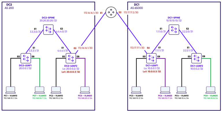
We introduced an additional router that interconnects DC2-Leaf1 to DC1-Leaf1. This router provides IP routing between the two Data Centers.
Configuration of Multi-site DCI
Step 1: Adding new loopbacks on the border VTEPs to be used as external IPs
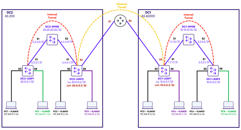
In multi-site EVPN-VXLAN deployments, an external IP is required on each border leaf VTEP to clearly separate internal fabric connectivity from inter-site DCI traffic. The internal source IP is used for VXLAN tunnels within the local data center, while the external IP is specifically used to establish VXLAN tunnels toward remote sites. This separation ensures that the border VTEP can independently identify, terminate, and re-originate overlay traffic depending on whether it is local or destined for another site.
DC1-LEAF1
interface Loopback 1
 ip address 10.0.0.3/32
DC2-LEAF2
interface Loopback 1
 ip address 20.0.0.3/32
Step 2: Configuration of routing between the two Data Centers
The new loopback 1 configured on both border VTEPs has to be able to communicate with each other in order to setup the BGP session between both VTEPs.
In our setup, Static routing is configured between the two border VTEPs.
DC1-LEAF1
interface Ethernet6
 no shutdown
 ip address 172.17.17.1/30
!

ip route 20.0.0.3/32 172.17.17.2
DC2-LEAF2
interface Ethernet2
 no shutdown
 ip address 172.16.16.1/30
!

ip route 10.0.0.3/32 172.16.16.2
Step 3: BGP Configuration between the two Border VTEPs
fabric-external command.
The key purpose of fabric-external is to explicitly mark the neighbor as part of a different EVPN fabric. This allows the border leaf to differentiate between internal EVPN peers (within the same site) and external peers (remote sites), and apply different route handling logic accordingly.
With this distinction in place, EVPN Type-2 and Type-5 routes are exchanged across sites but are re-originated at the border leaf using local route distinguishers and route targets, ensuring each fabric maintains its own routing identity.
Type-3 (IMET) routes are not re-originated across the border; only locally generated IMET routes are advertised. Type-1 and Type-4 routes are not propagated between fabrics and remain locally consumed.
Overall, the fabric-external configuration provides a clear EVPN control-plane boundary between data centers while still allowing selective and consistent route exchange across the multi-site infrastructure.
DC1-LEAF1
router bgp 65000
 neighbor 20.0.0.3
  ebgp-multihop 255
  remote-as external
  update-source 10.0.0.3
  !
  address-family l2vpn evpn
   activate
   fabric-external
DC2-LEAF2
router bgp 200
 neighbor 10.0.0.3
  ebgp-multihop 255
  remote-as external
  update-source 20.0.0.3
  !
  address-family l2vpn evpn
   activate
   fabric-external
Step 4: Addition of the external-ip under the VTEP
external-ip under the VTEP configuration is what enables multi-site awareness in the VXLAN overlay. In a single-site EVPN-VXLAN design, a VTEP typically only needs a source-ip, which is used as the tunnel endpoint for all VXLAN encapsulation within the local fabric.
In a multi-site DCI setup, however, the VTEP must distinguish between two types of VXLAN connectivity: internal tunnels (within the local data center) and external tunnels (toward remote sites). The external-ip is introduced specifically for this purpose. It represents the VTEP address that remote sites use as the VXLAN tunnel endpoint when establishing inter-site connectivity.
DC1-LEAF1
interface vxlan vtep1
 source-ip 10.0.0.1
 external-ip 10.0.0.3
 map vni 100010 vlan 10
 map vni 100020 vlan 20
 map vni 100030 vlan 30
DC2-LEAF2
interface vxlan vtep2
 source-ip 20.0.0.2
 external-ip 20.0.0.3
 map vni 100010 vlan 10
 map vni 100020 vlan 20
 map vni 100030 vlan 30
Step 5: Important note
In some multi-site EVPN-VXLAN deployments, a VLAN may exist on the border VTEP only for inter-DC extension and may not have any active local access ports. In such cases, the VLAN can remain operationally down due to autostate behavior, which prevents the associated VNI and bridge domain from becoming fully active. This can break cross–data center connectivity even when EVPN routes are correctly exchanged. Enablingno autostate on the VLAN interface ensures that the VLAN remains in an “up” state regardless of local port membership, allowing the border VTEP to properly instantiate the bridge domain and forward VXLAN traffic for that VLAN across sites. DC1-LEAF1
interface Vlan30
 no autostate
DC2-LEAF2
interface Vlan30
 no autostate
Verification
The commandshow vxlan tunnel on both border VTEPs shows us the internal and external tunnels established and also show in the diagram below. DC1-LEAF1
DC1-LEAF1# show vxlan tunnel

        Name                SIP                DIP           source    Group     D-VNI     operstatus
        ====                ===                ===           ======    =====     =====     ==========
   EVPN_10.0.0.2          10.0.0.1           10.0.0.2         EVPN    internal     no       oper_up
 EVPN_20.0.0.3-Ext        10.0.0.3           20.0.0.3         EVPN    external     no       oper_up
DC2-LEAF2
DC2-LEAF2# show vxlan tunnel

        Name                SIP                DIP           source    Group     D-VNI     operstatus
        ====                ===                ===           ======    =====     =====     ==========
 EVPN_10.0.0.3-Ext        20.0.0.3           10.0.0.3         EVPN    external     no       oper_up
   EVPN_20.0.0.1          20.0.0.2           20.0.0.1         EVPN    internal     no       oper_up
Traffic Test
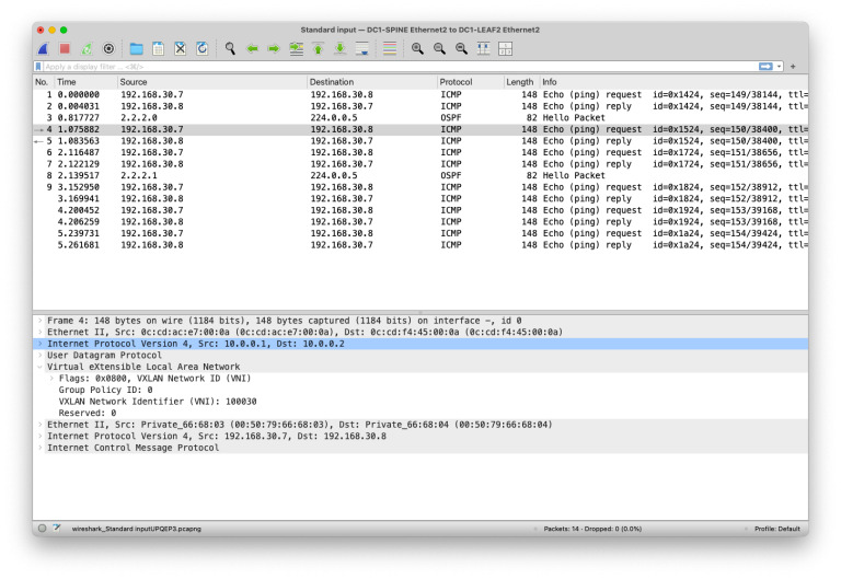
We will verify the dataplane by doing a ping test between PC7 (VLAN 30) in DC2 and PC8 (VLAN 30) in DC1.
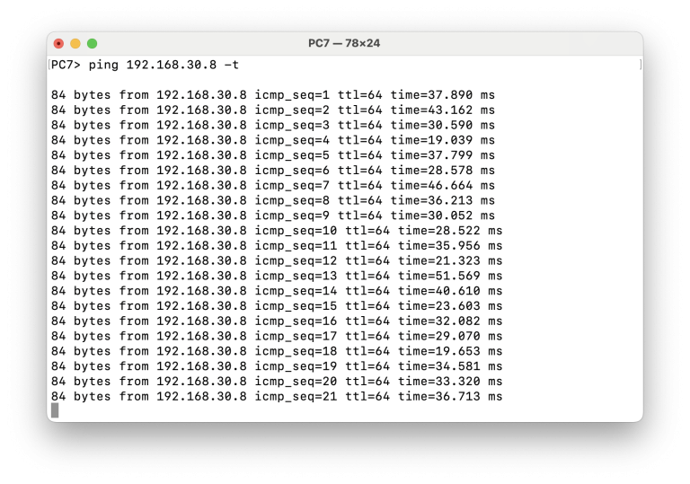
And we will capture traffic at three locations for further analysis.
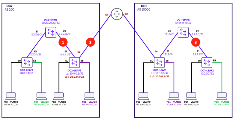
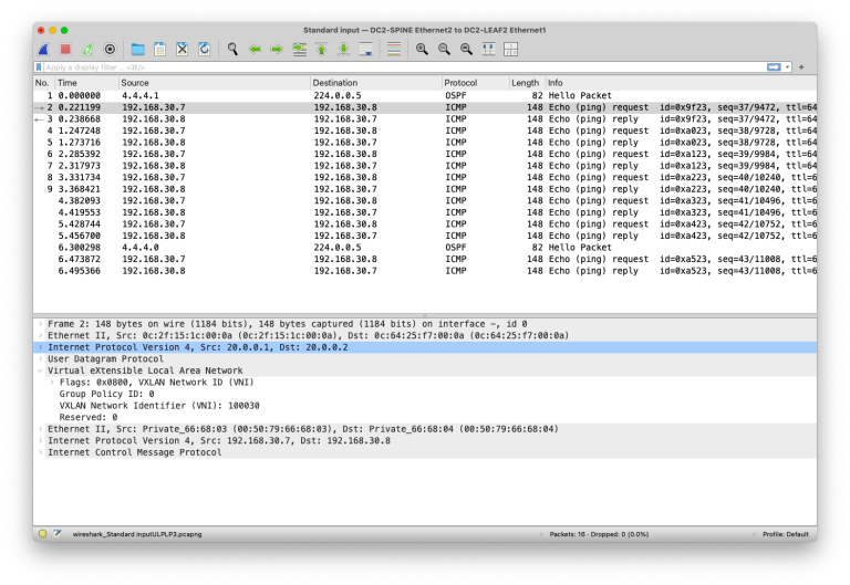
Capture point 1
We capture the traffic on the link between the DC2-SPINE and DC2-LEAF2.
Notice the VXLAN tunnel source and destination:
- Source: 20.0.0.1 (DC2-LEAF1)
- Destination: 20.0.0.2 (DC2-LEAF2)
Capture point 2
We capture the traffic on the link between the two data Centers Notice the VXLAN tunnel source and destination:- Source: 20.0.0.3 (DC2-LEAF2)
- Destination: 10.0.0.3 (DC2-LEAF1)
external-ip configured on both border VTEPs 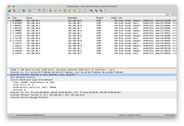
Capture point 3
We capture the traffic on the link between the DC1-SPINE and DC1-LEAF2.
Notice the VXLAN tunnel source and destination:
- Source: 10.0.0.1 (DC1-LEAF1)
- Destination: 10.0.0.2 (DC1-LEAF2)