SONIC VLAN Configuration
In this article we will explore how configure VLAN on Enterprise SONiC. We will cover the following topics:
- Access ports
- Trunk ports
- VLAN memberships
- VLAN Interfaces
Creating VLANs
To create VLAN 10, use the following command:
sonic# interface vlan 10
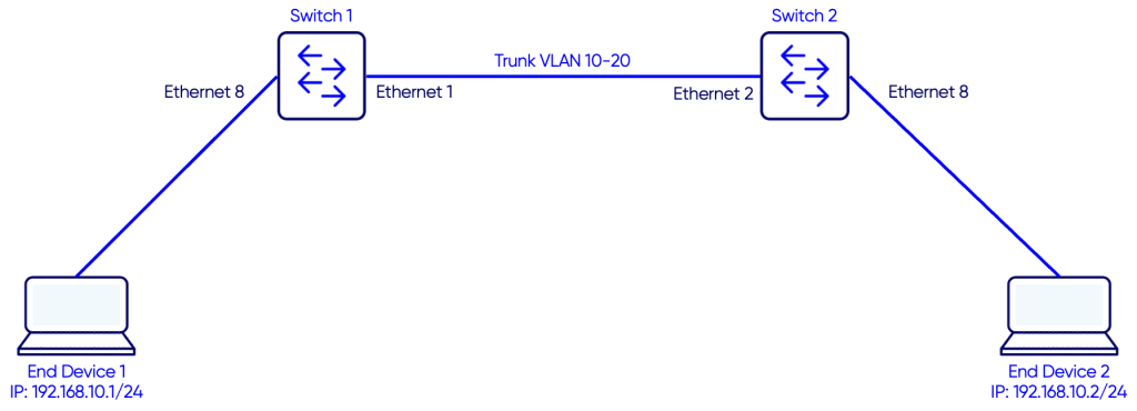
On Switch-1
Switch-1# configure terminal
Switch-1(config)# interface Vlan 10
Switch-1(conf-if-Vlan10)#
On Switch-2
Switch-2# configure terminal
Switch-2(config)# interface Vlan 10
Switch-2(conf-if-Vlan10)#
Access Ports Configuration
An access port sends and receives untagged frames from connected devices. To assign an interface to a specific VLAN as access-port , use the command:
switchport access Vlan vlan-id
On Switch-1
Switch-1# configure terminal
Switch-1(config)# interface Ethernet 8
Switch-1(conf-if)# switchport access vlan 10
Switch-1(conf-if)# no shutdown
On Switch-2
Switch-2# configure terminal
Switch-2(config)# interface Ethernet 8
Switch-2(conf-if)# switchport access vlan 10
Switch-1(conf-if)# no shutdown
To remove an interface from the access VLAN, enter the command:
no switchport access vlan
Trunk Ports Configuration
A trunk port carries traffic for multiple VLANs.It sends and receives tagged frames for allowed VLANs.
By default, no VLANs are allowed on a trunk interface. To configure the allowed VLANs on a trunk interface, use the command:
switchport trunk allowed Vlan {vlan-list | {add | remove | except} vlan-list | none | all}
On Switch-1
Switch-1# configure terminal
Switch-1(config)# interface Ethernet 1
Switch-1(conf-if)# switchport trunk allowed Vlan 10,20
Switch-1(conf-if)# no shutdown
On Switch-2
Switch-2# configure terminal
Switch-2(config)# interface Ethernet 2
Switch-2(conf-if)# switchport trunk allowed Vlan 10,20
Switch-2(conf-if)# no shutdown
Verifying VLAN configuration
Use the command show vlan to verify the configuration.
On Switch-1
Switch-1# show Vlan
Q: A - Access (Untagged), T - Tagged
NUM        Status      Q Ports            Autostate   Dynamic
10         Active      T  Ethernet1        Enable      No
                       A  Ethernet8                    No
20         Active      T  Ethernet1        Enable      No
On Switch-2
Switch-2# show Vlan
Q: A - Access (Untagged), T - Tagged
NUM        Status      Q Ports            Autostate   Dynamic
10         Active      T  Ethernet1        Enable      No
                       A  Ethernet8                    No
20         Active      T  Ethernet1        Enable      No
Verifying traffic between the two end devices
To verify our configuration we will ping from PC1 to PC2.
PC1> show

NAME   IP/MASK              GATEWAY           MAC                LPORT  RHOST:PORT
PC1    192.168.10.1/24      0.0.0.0           00:50:79:66:68:00  20046  127.0.0.1:20047
       fe80::250:79ff:fe66:6800/64

PC1> ping 192.168.10.2

84 bytes from 192.168.10.2 icmp_seq=1 ttl=64 time=13.773 ms
84 bytes from 192.168.10.2 icmp_seq=2 ttl=64 time=8.745 ms
84 bytes from 192.168.10.2 icmp_seq=3 ttl=64 time=11.953 ms
84 bytes from 192.168.10.2 icmp_seq=4 ttl=64 time=13.511 ms
84 bytes from 192.168.10.2 icmp_seq=5 ttl=64 time=12.028 ms
Verifying MAC address-table on the two switches
We can also verify the MAC address tables on the two switches
On Switch-1
Switch-1# show mac address-table
-----------------------------------------------------------
VLAN         MAC-ADDRESS         TYPE         INTERFACE
-----------------------------------------------------------
10          00:50:79:66:68:01   DYNAMIC       Ethernet1
10          00:50:79:66:68:00   DYNAMIC       Ethernet8
On Switch-2
Sonic-2# show mac address-table
-----------------------------------------------------------
VLAN         MAC-ADDRESS         TYPE         INTERFACE
-----------------------------------------------------------
10          00:50:79:66:68:00   DYNAMIC       Ethernet2
10          00:50:79:66:68:01   DYNAMIC       Ethernet8
Notes
In show Vlan output:
NUM— VLAN ID numberStatus— VLAN status displays as Active or Inactive.Active— A VLAN member is present and the line protocol for at least one VLAN member is up.Inactive— No VLAN member is present or the line protocol for all VLAN members is down.Q— Displays the 802.1Q mode of a VLAN member interface:T— Tagged VLAN memberA— Access VLAN memberAutostate— Displays the VLAN autostate mode: Enable or Disable.Dynamic— Yes indicates a RADIUS-supplied VLAN. No indicates a static VLAN that was manually configured.