SONiC EVPN-VXLAN Multi-Homing and Uplink Tracking
This article describes EVPN multi-homing in an EVPN-VXLAN fabric using Enterprise SONiC, a feature that allows a server or network device to connect to multiple leaf switches simultaneously while appearing as a single logical attachment point from the overlay’s perspective.
Multi-homing is achieved through Ethernet Segment Identifiers (ESI), which allow two or more VTEPs to advertise shared attachment to the same endpoint. EVPN then uses EVPN Type-1 and Type-4 routes to coordinate designated forwarder (DF) election, split-horizon filtering, and MAC/IP reachability across all member VTEPs.
We will also cover uplink tracking, a complementary mechanism that monitors the state of upstream links on a leaf switch toward the spines and automatically brings down access ports when uplink connectivity is lost — preventing traffic blackholing in multi-homed topologies.
We will cover:
- EVPN multi-homing architecture overview
- Ethernet Segment configuration (ESI and LAG)
- EVPN Type-1 and Type-4 route behaviour
- Uplink tracking configuration and behaviour
- Verification and validation
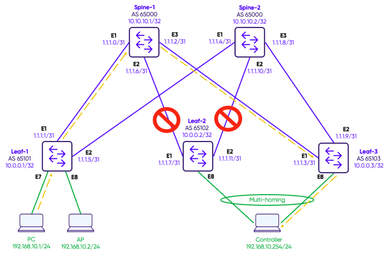
Topology
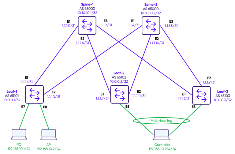
The underlay (OSPF) and overlay (EVPN-VXLAN L2VNI/L3VNI) configuration will not be covered in detail here, as they are already described in Guide 17 – EVPN-VXLAN Configuration and Guide 18 – EVPN-VXLAN L3VNI. However, to provide full context, the complete baseline configuration scripts for the 2 spines and 3 leaves used in this topology are provided below before diving into the multi-homing configuration.
Configuration of the underlay and overlay
The configuration are provided below:
SPINE-1
!
interface Loopback 0
 ip address 10.10.10.1/32
!
interface Ethernet1
 description "Link to Leaf-1"
 mtu 9100
 speed 25000
 unreliable-los auto
 no shutdown
 ip address 1.1.1.0/31
!
interface Ethernet2
 description "Link to Leaf-2"
 mtu 9100
 speed 25000
 unreliable-los auto
 no shutdown
 ip address 1.1.1.2/31
!
interface Ethernet3
 description "Link to Leaf-3"
 mtu 9100
 speed 25000
 unreliable-los auto
 no shutdown
 ip address 1.1.1.6/31
!
router bgp 65000
 router-id 10.10.10.1
 log-neighbor-changes
 timers 60 180
 !
 address-family ipv4 unicast
  redistribute connected
  maximum-paths 1
  maximum-paths ibgp 1
 !
 address-family l2vpn evpn
  advertise-all-vni
  dup-addr-detection
 !
 neighbor 1.1.1.1
  remote-as 65101
  !
  address-family ipv4 unicast
   activate
  !
  address-family l2vpn evpn
   activate
 !
 neighbor 1.1.1.3
  remote-as 65102
  !
  address-family ipv4 unicast
   activate
  !
  address-family l2vpn evpn
   activate
 !
 neighbor 1.1.1.7
  remote-as 65103
  !
  address-family ipv4 unicast
   activate
  !
  address-family l2vpn evpn
   activate
!
SPINE-2
!
interface Loopback 0
 ip address 10.10.10.2/32
!
interface Ethernet1
 description "Link to Leaf-1"
 mtu 9100
 speed 25000
 unreliable-los auto
 no shutdown
 ip address 1.1.1.4/31
!
interface Ethernet2
 description "Link to Leaf-2"
 mtu 9100
 speed 25000
 unreliable-los auto
 no shutdown
 ip address 1.1.1.10/31
!
interface Ethernet3
 description "Link to Leaf-3"
 mtu 9100
 speed 25000
 unreliable-los auto
 no shutdown
 ip address 1.1.1.8/31
!
router bgp 65000
 router-id 10.10.10.2
 log-neighbor-changes
 timers 60 180
 !
 address-family ipv4 unicast
  redistribute connected
  maximum-paths 1
  maximum-paths ibgp 1
 !
 address-family l2vpn evpn
  advertise-all-vni
  dup-addr-detection
 !
 neighbor 1.1.1.5
  remote-as 65101
  !
  address-family ipv4 unicast
   activate
  !
  address-family l2vpn evpn
   activate
 !
 neighbor 1.1.1.9
  remote-as 65103
  !
  address-family ipv4 unicast
   activate
  !
  address-family l2vpn evpn
   activate
 !
 neighbor 1.1.1.11
  remote-as 65102
  !
  address-family ipv4 unicast
   activate
  !
  address-family l2vpn evpn
   activate
!
LEAF-1
!
interface Vlan10
 description "Green-Servers VLAN"
!
interface Loopback 0
 ip address 10.0.0.1/32
!
interface Ethernet1
 description "Link to Spine-1"
 mtu 9100
 speed 25000
 unreliable-los auto
 no shutdown
 ip address 1.1.1.1/31
!
interface Ethernet2
 description "Link to Spine-2"
 mtu 9100
 speed 25000
 unreliable-los auto
 no shutdown
 ip address 1.1.1.5/31
!
interface Ethernet7
 mtu 9100
 speed 25000
 unreliable-los auto
 no shutdown
 switchport access Vlan 10
!
interface Ethernet8
 mtu 9100
 speed 25000
 unreliable-los auto
 no shutdown
 switchport access Vlan 10
!


router bgp 65101
 router-id 10.0.0.1
 log-neighbor-changes
 timers 60 180
 !
 address-family ipv4 unicast
  redistribute connected
  maximum-paths 1
  maximum-paths ibgp 1
 !
 address-family l2vpn evpn
  advertise-all-vni
  dup-addr-detection
 !
 neighbor 1.1.1.0
  remote-as 65000
  !
  address-family ipv4 unicast
   activate
  !
  address-family l2vpn evpn
   activate
 !
 neighbor 1.1.1.4
  remote-as 65000
  !
  address-family ipv4 unicast
   activate
  !
  address-family l2vpn evpn
   activate
!

interface vxlan vtep1
 source-ip 10.0.0.1
 qos-mode pipe dscp 0
 map vni 100010 vlan 10
!
LEAF-2
!
interface Vlan10
 description "Green-Servers VLAN"
!
interface Loopback 0
 ip address 10.0.0.2/32
!
interface Ethernet1
 description "Link to Spine-1"
 mtu 9100
 speed 25000
 unreliable-los auto
 no shutdown
 ip address 1.1.1.3/31
 link state track UPLINKS upstream
!
interface Ethernet2
 description "Link to Spine-2"
 mtu 9100
 speed 25000
 unreliable-los auto
 no shutdown
 ip address 1.1.1.11/31
 link state track UPLINKS upstream
!
interface Ethernet3
 mtu 9100
 speed 25000
 unreliable-los auto
 no shutdown
 switchport access Vlan 10
!
interface Ethernet8
 mtu 9100
 speed 25000
 unreliable-los auto
 channel-group 1
 no shutdown
!


router bgp 65102
 router-id 10.0.0.2
 log-neighbor-changes
 timers 60 180
 !
 address-family ipv4 unicast
  redistribute connected
  maximum-paths 1
  maximum-paths ibgp 1
 !
 address-family l2vpn evpn
  advertise-all-vni
  dup-addr-detection
 !
 neighbor 1.1.1.2
  remote-as 65000
  !
  address-family ipv4 unicast
   activate
  !
  address-family l2vpn evpn
   activate
 !
 neighbor 1.1.1.10
  remote-as 65000
  !
  address-family ipv4 unicast
   activate
  !
  address-family l2vpn evpn
   activate
!

interface vxlan vtep2
 source-ip 10.0.0.2
 qos-mode pipe dscp 0
 map vni 100010 vlan 10
!

interface PortChannel1
 switchport trunk allowed Vlan 10
 no shutdown
 system-mac 00:00:00:00:11:11
 !
 evpn ethernet-segment auto-system-mac
 !
!
LEAF-3
!
interface Vlan10
 description "Green-Servers VLAN"
!
interface Loopback 0
 ip address 10.0.0.3/32
!
interface Ethernet1
 description "Link to Spine-1"
 mtu 9100
 speed 25000
 unreliable-los auto
 no shutdown
 ip address 1.1.1.7/31
 link state track UPLINKS upstream
!
interface Ethernet2
 description "Link to Spine-2"
 mtu 9100
 speed 25000
 unreliable-los auto
 no shutdown
 ip address 1.1.1.9/31
 link state track UPLINKS upstream
!
interface Ethernet3
 mtu 9100
 speed 25000
 unreliable-los auto
 no shutdown
 switchport access Vlan 10
!
interface Ethernet8
 mtu 9100
 speed 25000
 unreliable-los auto
 channel-group 1
 no shutdown
!


router bgp 65103
 router-id 10.0.0.3
 log-neighbor-changes
 timers 60 180
 !
 address-family ipv4 unicast
  redistribute connected
  maximum-paths 1
  maximum-paths ibgp 1
 !
 address-family l2vpn evpn
  advertise-all-vni
  dup-addr-detection
 !
 neighbor 1.1.1.6
  remote-as 65000
  !
  address-family ipv4 unicast
   activate
  !
  address-family l2vpn evpn
   activate
 !
 neighbor 1.1.1.8
  remote-as 65000
  !
  address-family ipv4 unicast
   activate
  !
  address-family l2vpn evpn
   activate
!

interface vxlan vtep3
 source-ip 10.0.0.3
 qos-mode pipe dscp 0
 map vni 100010 vlan 10
!

interface PortChannel1
 switchport trunk allowed Vlan 10
 no shutdown
 system-mac 00:00:00:00:11:11
 !
 evpn ethernet-segment auto-system-mac
 !
!
Configuration of Multi-homing
Step 1: Port-Channel and VLAN Membership
The first step is to create the port-channel on both multi-homing leaf switches and assign it to the appropriate VLANs. The port-channel will serve as the multi-homed interface toward the connected server.
A system-mac address must also be configured on the port-channel. In an EVPN multi-homing setup, both leaf switches must share the same system-mac on the port-channel so that the server sees a single consistent LACP peer regardless of which leaf it is communicating with. Without this, LACP negotiation would fail as each leaf would present a different system MAC to the server.
LEAF-2
interface PortChannel1
 switchport trunk allowed Vlan 10
 no shutdown
 system-mac 00:00:00:00:11:11
 !
 evpn ethernet-segment auto-system-mac
 !
!
interface Ethernet8
channel-group 1
LEAF-3
interface PortChannel1
 switchport trunk allowed Vlan 10
 no shutdown
 system-mac 00:00:00:00:11:11
 !
 evpn ethernet-segment auto-system-mac
 !
!
interface Ethernet8
channel-group 1
The system-mac must be identical on both leaves and should be a value that does not conflict with any real interface MAC address in the fabric.
Step 2: Uplink Tracking Configuration
Uplink tracking ensures that if a leaf switch loses all connectivity to the spine layer, its access-facing port-channel is automatically brought down. This forces the multi-homed server to fail over to the other leaf, preventing traffic blackholing in a situation where the leaf is still reachable from the server but has no upstream path.
A link state tracking group is created and the uplink interfaces toward the spines are assigned as upstream members. When all upstream members go down, the leaf itself will lose fabric reachability, which EVPN will detect and handle through the normal withdrawal of EVPN routes.
LEAF-2
!
link state track UPLINKS
  downstream all-evpn-es
!
interface Ethernet1
 description "Link to Spine-1"
link state track UPLINKS upstream
!
interface Ethernet2
 description "Link to Spine-2"
link state track UPLINKS upstream
LEAF-3
interface PortChannel1
 switchport trunk allowed Vlan 10
 no shutdown
 system-mac 00:00:00:00:11:11
 !
 evpn ethernet-segment auto-system-mac
 !
!
interface Ethernet8
channel-group 1
Verification commands
Ethernet Segment State
The first command to verify multi-homing isshow evpn es. It confirms that the Ethernet Segment is locally instantiated on the leaf, that the remote peer (the other multi-homing leaf) is visible, and that the DF election has completed. LEAF-2
Leaf-2# show evpn es
Type: B bypass, L local, R remote, N non-DF
ESI                            Type ES-IF                 VTEPs
03:00:00:00:00:11:11:00:00:01  LR   PortChannel1          10.0.0.3
LEAF-3
Leaf-3# show evpn es
Type: B bypass, L local, R remote, N non-DF
ESI                            Type ES-IF                 VTEPs
03:00:00:00:00:11:11:00:00:01  LRN  PortChannel1          10.0.0.2
Ethernet Segment per EVI
Theshow evpn es-evi detailLEAF-3
Leaf-3# show evpn es-evi detail
VNI 100010 ESI: 03:00:00:00:00:11:11:00:00:01
Type: L
Ready for BGP: yes
show PortChannel summary confirms the LAG is operational and that the member interface has successfully negotiated LACP with the server. LEAF-3
Leaf-3# show PortChannel summary
Flags(oper-status):  D - Down U - Up (portchannel) P - Up in portchannel (members) I - LACP individual
--------------------------------------------------------------------
Group    PortChannel      Type    Protocol    Member Ports
--------------------------------------------------------------------
1        PortChannel1(U)  Eth     LACP        Ethernet8(P)
PortChannel1 (U) confirms the LAG is up, and Ethernet8 (P) confirms the member port has successfully joined the port-channel via LACP.
BGP EVPN Route Verification
The show bgp l2vpn evpn route output shows the full picture of the multi-homing control plane. The key route types to look for are:
- Type-1 (EAD — Ethernet Auto-Discovery): advertised per-ES and per-EVI by both Leaf2 and Leaf3, used to signal ES membership and enable fast failover.
- Type-4 (ES — Ethernet Segment): used for DF election between the two multi-homing peers. Both leaves advertise a Type-4 route for the shared ESI, and the DF is elected based on the preference value.
- Type-2 (MAC/IP): the server MAC
0c:fd:a9:f0:00:0ais advertised by both Leaf2 and Leaf3, each carrying the ESI in the route — signalling to the rest of the fabric that this MAC is reachable via a multi-homed segment.
LEAF-3
*>   [1]:[4294967295]:[03:00:00:00:00:11:11:00:00:01]:[128]:[::]:[0]
                    10.0.0.2                           RT:65102:100010 ESI-label-Rt:AA
*>   [1]:[4294967295]:[03:00:00:00:00:11:11:00:00:01]:[128]:[::]:[0]
                    10.0.0.3                           RT:65103:100010 ESI-label-Rt:AA

*>   [4]:[03:00:00:00:00:11:11:00:00:01]:[32]:[10.0.0.2]
                    10.0.0.2                           DF: (alg: 2, pref: 32767)
*>   [4]:[03:00:00:00:00:11:11:00:00:01]:[32]:[10.0.0.3]
                    10.0.0.3                           DF: (alg: 2, pref: 32767)

*>   [2]:[0]:[48]:[0c:fd:a9:f0:00:0a]
                    10.0.0.2                           ESI:03:00:00:00:00:11:11:00:00:01
*>   [2]:[0]:[48]:[0c:fd:a9:f0:00:0a]
                    10.0.0.3                           ESI:03:00:00:00:00:11:11:00:00:01
Uplink Tracking Verification
Theshow link state tracking UPLINKS command confirms that the tracking group is active, both upstream links are healthy, and the downstream port-channel is up. LEAF-3
Leaf-3# show link state tracking UPLINKS
Name: UPLINKS
Description:
Timeout: 60
Startup remaining time: 0 seconds
Upstream:
    Ethernet2 (Up)
    Ethernet1 (Up)
Downstream:
    PortChannel1 (Up)
As long as at least one upstream interface remains up, the downstream PortChannel1 stays operational. If both upstream links fail simultaneously, the tracking group will bring down PortChannel1 after the 60-second timeout, triggering LACP failover on the server to the other multi-homing leaf.
Traffic Test
We will verify the dataplane by doing a ping test between the PC (192.168.10.1) and the controller (192.168.10.254).
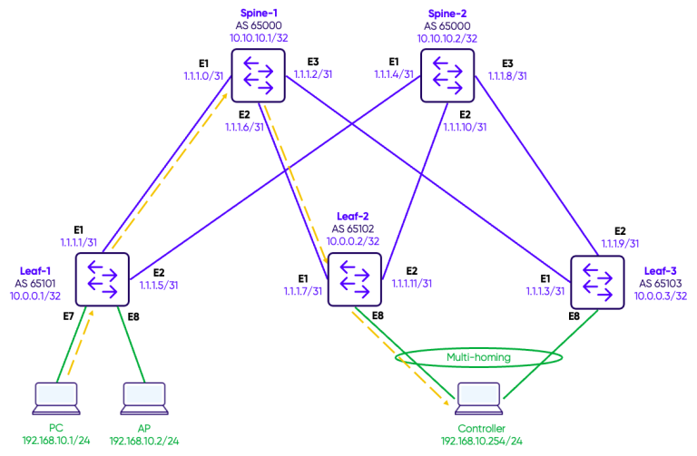
In a normal situation the ICMP requests and reply follow the path Leaf-1 – Spine-1 – Leaf-2.
We will verify the dataplane by doing a ping test between the PC (192.168.10.1) and the controller (192.168.10.254).
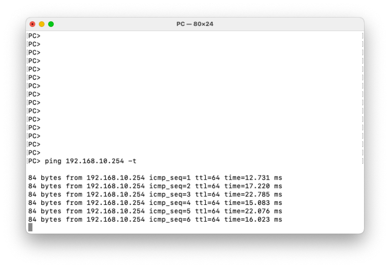
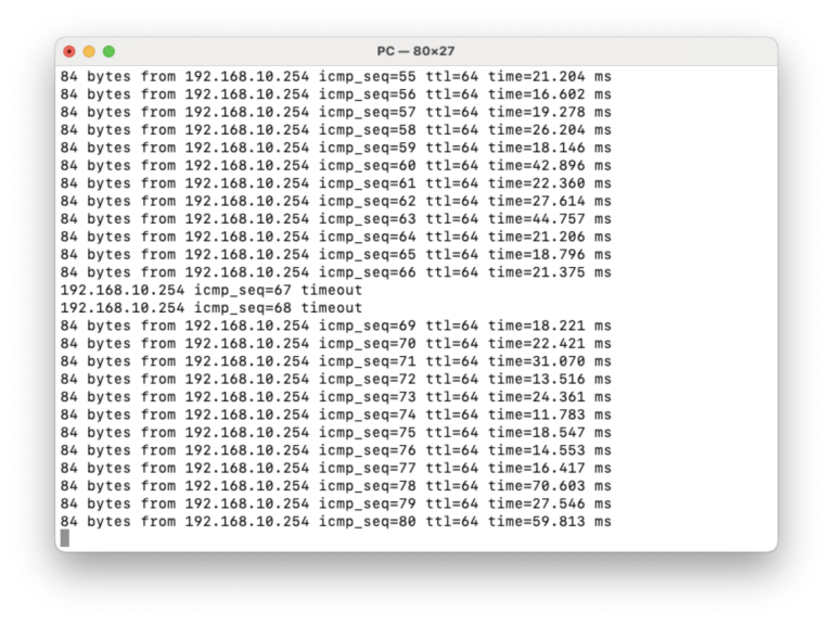
First step is to test that Multi-homing is operating as expected. While the ping is running, we will simulate a failure on the link between the multi-homed device (controller) and Leaf-2.
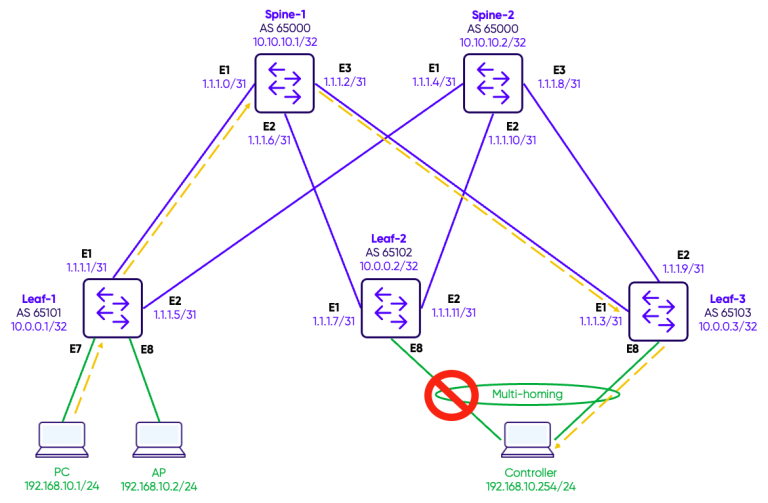
Traffic converges on Leaf-3 and we observe a couple of ping timeouts.
We then reestablish the link between the multi-homed device (controller) and Leaf-2.
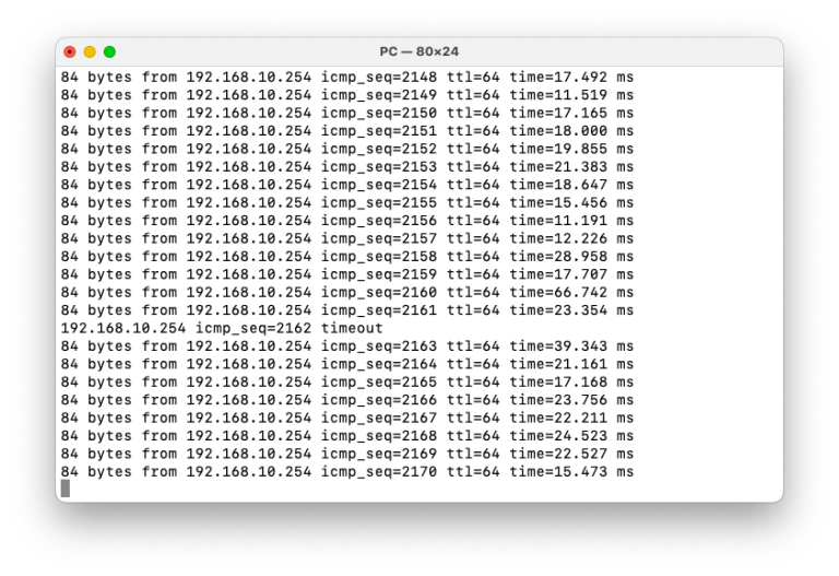
Next step is to test that the link state tracking works as expected. We simulate a failure of the two links on Leaf-2 connecting to Spine-1 and Spine-2.
Traffic converges on Leaf-3 and we observe a ping timeout.
Notice the link state tracking on Leaf-2. Both upstream links are down and hence the PortChannel1 was automatically disabled.
LEAF-3
Leaf-2# show link state tracking UPLINKS
Name: UPLINKS
Description:
Timeout: 60
Startup remaining time: 0 seconds
Upstream:
    Ethernet2 (Down)
    Ethernet1 (Down)
Downstream:
    PortChannel1 (Disabled)
Conclusion
EVPN multi-homing and link state tracking are complementary features that together deliver a robust, loop-free active-active redundancy model at the access layer.
EVPN multi-homing, through ESI and the associated Type-1 and Type-4 routes, allows multiple leaf switches to share attachment to the same server or network device while the control plane handles DF election, split-horizon filtering, and consistent MAC reachability across the fabric.
Link state tracking adds an important safeguard to this model. A leaf switch that has lost all upstream connectivity would otherwise remain a valid LACP peer for the connected server, silently blackholing traffic. With uplink tracking in place, that leaf proactively signals its unavailability by bringing down the port-channel, forcing an immediate LACP failover to the healthy peer.
Together, these two features ensure that server-facing redundancy is handled both at the overlay control plane level through EVPN, and at the physical link level through LACP and uplink tracking — giving operators a simple, standards-based, and highly resilient dual-homing architecture on Enterprise SONiC.