SONiC EVPN-VXLAN L3VNI
In this article, we explore how to deploy EVPN-VXLAN on Enterprise SONiC, using multiple L2VNIs for Layer 2 segmentation and a L3VNI to enable inter-subnet routing within the tenant.
This design is commonly used in enterprise and data center fabrics where a single tenant requires multiple VLANs with Layer 3 connectivity, while still benefiting from VXLAN scalability and EVPN control plane.
This article is a continuation of article 17 – SONiC EVPN-VXLAN Configuration which covered:
- EVPN-VXLAN single-tenant architecture
- BGP EVPN configuration
- VXLAN tunnel configuration
- VLAN and L2VNI configuration
Here we will explore adding a second L2VNI and L3VNI configuration to allow servers in different VNIs to communicate between each other.
Our design consists of
- One VRF representing a tenant
- Two VLANs, each mapped to a unique L2VNI
- An L3VNI associated with the VRF
The L3VNI enables distributed anycast routing, allowing traffic between VLANs to be routed locally on each leaf switch.
Topology
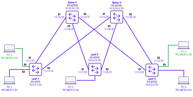
We configure two VLANs, each of the VLANs has access ports on the various leafs connected to PC simulating servers.
On each leaf switch, a VXLAN Tunnel Endpoint (VTEP) interface is configured to encapsulate tenant traffic for transport across the underlay fabric. The VTEP is assigned a source IP, typically the loopback address, which uniquely identifies the switch in the VXLAN overlay. Each VLAN is then mapped to a unique VXLAN Network Identifier (VNI), allowing the switch to encapsulate and forward traffic for multiple VLANs within the same tenant. For example, VLAN 10 is mapped to VNI 100010 and VLAN 20 mapped to VNI 100020.
To validate the EVPN-VXLAN configuration, we first test connectivity between hosts within the same tenant. Since both VLANs belong to the same VRF and a single L3VNI is configured, the PCs can communicate across VLANs through the L3VNI, demonstrating inter-VLAN routing within the tenant. For completeness, we also test connectivity with hosts in other tenants, which should fail by design due to VRF-based isolation. This testing confirms that the EVPN overlay correctly separates tenant traffic while enabling intra-tenant routing.
Configuration
Step 1: Adding a second L2VNI
We previously configured VNI 100010 in the previous article and mapped VLAN 10 to it. Now, we will add a second VNI 100020 and map VLAN 20 to it.
Leaf-1
interface Vlan20
 description "Green-Servers"
!
interface Ethernet4
 no shutdown
 switchport access Vlan 20

interface vxlan vtep1
 source-ip 10.0.0.1
 map vni 100020 vlan 20
 map vni 100010 vlan 10
Leaf-2
interface Vlan20
 description "Green-Servers"
!
interface Ethernet4
 no shutdown
 switchport access Vlan 20

interface vxlan vtep2
 source-ip 10.0.0.2
 map vni 100020 vlan 20
 map vni 100010 vlan 10
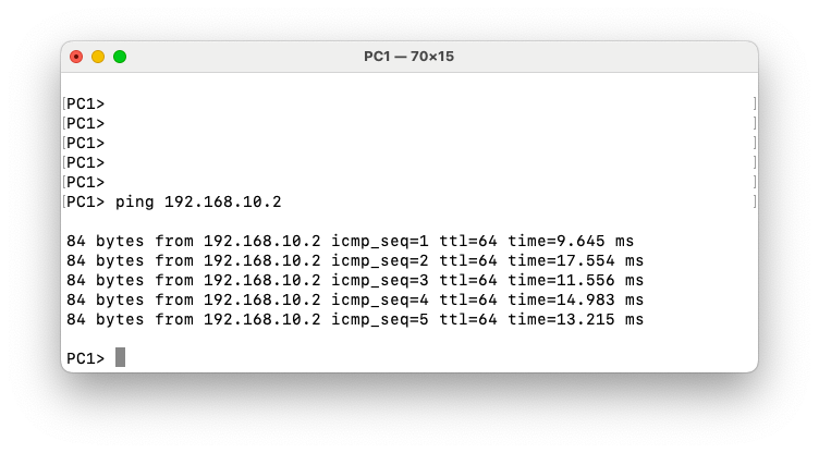
Within VLAN 20, hosts can communicate successfully. This is because all traffic within an L2VNI is switched at Layer 2 across the VXLAN fabric.
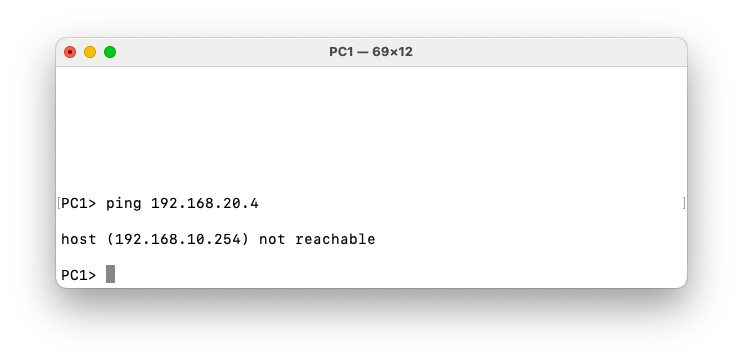
However, communication between VLAN 10 (VNI 100020) and VLAN 20 (VNI 100020) fails. This behavior is expected because inter-VLAN routing in an EVPN-VXLAN fabric requires a Layer-3 VNI (L3VNI). In the current configuration, each VLAN is mapped only to its own Layer-2 VNI, providing Layer-2 extension across the VXLAN overlay. Since no L3VNI and associated VRF are configured, the fabric does not perform routing between the two VNIs. As a result, traffic cannot traverse from one L2VNI to another, even if both belong to the same tenant.
Step 2: L3VNI Configuration
L2VNIs allow hosts within the same VLAN to communicate by bridging traffic over VXLAN. However, communication between different VLANs (for example VLAN 10 and VLAN 20) requires Layer-3 routing.
In traditional networks routing happens on a centralized L3 switch. Hosts use that switch as their default gateway.
In EVPN-VXLAN, we want distributed routing. Traffic should not hairpin to a central device. This is where the L3VNI comes in.
The L3VNI:
- Carries IP prefixes (EVPN Type-5 routes)
- Enables routing between L2VNIs
- Binds all VLANs in the same VRF together
To make routing distributed, we configure on every VTEP:
- The same gateway IP
- The same MAC address
Why do we use the same MAC and the same IP? Because let’s say Hosts in VLAN 10 use 192.168.10.254 as their default gateway. Then Every leaf responds with the same IP and same virtual MAC (00:00:22:22:22:22)
So from the host perspective, the gateway exists locally on every leaf.
L2VNIs allow hosts within the same VLAN to communicate by bridging traffic over VXLAN. However, communication between different VLANs (for example VLAN 10 and VLAN 20) requires Layer-3 routing.
In traditional networks, routing typically happens on a centralized Layer-3 switch. Hosts use that switch as their default gateway.
In an EVPN-VXLAN fabric, the goal is to provide distributed routing. Traffic should not hairpin through a central device. Instead, routing should occur on the leaf switch where the host is connected. This is achieved using an L3VNI associated with a VRF.
The L3VNI performs several functions:
- It carries IP prefix routes (EVPN Type-5 routes) for inter-subnet reachability
- It enables routing between different L2VNIs within the same VRF
- It provides the Layer-3 context that binds multiple VLANs belonging to the same tenant
To enable distributed routing, each VTEP is configured with the same default gateway for the subnet.
Specifically, every leaf switch uses:
- The same gateway IP address
- The same virtual gateway MAC address
For example, hosts in VLAN 10 may use 192.168.10.254 as their default gateway. Every leaf switch advertises and responds using that same IP address and a shared virtual MAC address (for example 00:00:22:22:22:22).
From the host’s perspective, the default gateway appears to exist locally on the connected leaf switch. As a result, traffic is routed immediately at the ingress leaf and then forwarded across the VXLAN fabric to the destination VTEP.
In EVPN, the distributed gateway MAC/IP pair is typically advertised using Type-2 routes, while Type-5 routes advertise IP prefixes across the L3VNI. This distinction is important because Type-2 routes provide host and gateway reachability, whereas Type-5 routes distribute routed prefixes between VTEPs.
Step 3: Anycast Gateways Configuration
Leaf-1
ip anycast-mac-address 00:00:22:22:22:22
ip anycast-address enable

ipv6 anycast-address enable

interface Vlan10
ip anycast-address 192.168.10.254/24
!
interface Vlan20
ip anycast-address 192.168.20.254/24
Leaf-2
ip anycast-mac-address 00:00:22:22:22:22
ip anycast-address enable

ipv6 anycast-address enable

interface Vlan10
ip anycast-address 192.168.10.254/24
!
Leaf-3
ip anycast-mac-address 00:00:22:22:22:22
ip anycast-address enable

ipv6 anycast-address enable

interface Vlan10
ip anycast-address 192.168.10.254/24
!
interface Vlan20
ip anycast-address 192.168.20.254/24
Verification
To verify our configuration we will test the ping from PC1 in VLAN 10 on Leaf-1 to PC4 in VLAN 20 on Leaf-2.
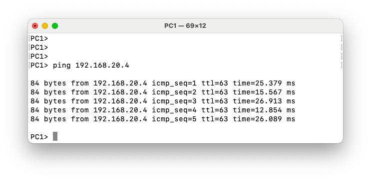
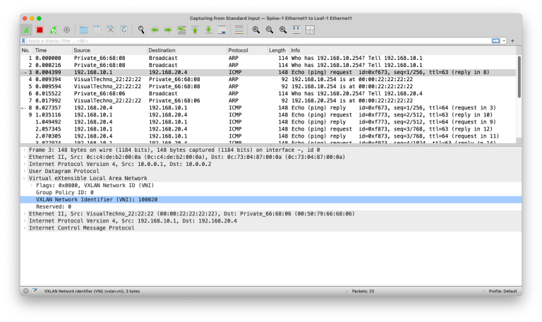
In the packet capture on the link between Leaf-1 and Spine-1, we can see the ICMP ping request from PC1 (192.168.10.1) to PC4 (192.168.20.4). Even though the ping originates from VLAN 10, the VXLAN header uses VNI 100020, which corresponds to the destination VLAN 20. This is because Leaf-1 encapsulates the routed packet into the VXLAN tunnel to reach the remote L2 segment where PC4 resides. The VXLAN packet is further encapsulated in an IP header with source IP 10.0.0.1 (Leaf-1 loopback) and destination IP 10.0.0.2 (Leaf-2 loopback), which are the endpoints of the VXLAN tunnel in the EVPN overlay. This layered encapsulation illustrates how EVPN-VXLAN separates L2 segments across the fabric while still enabling inter-VLAN routing via anycast gateways.