In this article we will explore how to configure Open Shortest Path First (OSPF) on Enterprise SONiC. We will cover:
- OSPF overview
- Enabling OSPF and setting router ID
- Configuring OSPF on interfaces
- Verifying OSPF neighbors and routes
OSPF Overview
OSPF is a dynamic Interior Gateway Protocol (IGP) that automatically exchanges routing information between routers within an Autonomous System. It uses link-state advertisements (LSAs) to build a complete topology and compute the shortest path using Dijkstra’s algorithm.
Key features:
- Hierarchical design with areas (most common: backbone area 0).
- Fast convergence.
- Load balancing across equal-cost paths.
Enterprise SONiC uses FRR packages for running routing protocols. OSPFv2 is also adapted from a customized FRR software package. The OPSFv2 routing daemon resides within the BGP docker container along with other routing protocol daemons, such as BGP, static route.
OSPFv2 capabilities supported:
- OSPF configuration on Ethernet, loopback, VLAN, and port-channel IPv4 interfaces.
- OSPFv2 configuration on default and user-defined VRFs.
- Multiple OSPF areas and stub areas.
- Type-1 to Type-5 LSAs.
- Virtual links and Passive interfaces.
- BFD on OSPF interface sessions.
- Plain text and message digest (MD) password encryption.
- Type-3 Summary LSA prefix filtering and substitution.
- Route redistribution into OSPFv2, from route type BGP, static, connected, kernel, and default-route.
- Route-map based filtering in route redistribution.
- OSPF ECMP routes.
- 50K external route and 5K internal route prefix.
Topology
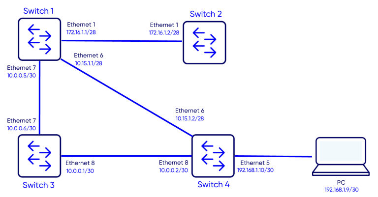
Objective
The objective of this configuration is to establish OSPF routing between four SONiC switches and verify:
- Successful OSPF neighbor adjacencies between all switches
- OSPF route propagation across the network
- End-to-end IP reachability from the PC to the 172.16.1.2/28 address configured on Switch-2
Configuration
Step 1 – Enabling OSPF and Setting Router IDs
Switch 1
Switch-1# configure terminal
Switch-1(config)# router ospf 1
Switch-1(config-router)# router-id 1.1.1.1
Switch 2
Switch-2# configure terminal
Switch-2(config)# router ospf 1
Switch-2(config-router)# router-id 2.2.2.2
Switch 3
Switch-3# configure terminal
Switch-3(config)# router ospf 1
Switch-3(config-router)# router-id 3.3.3.3
Switch 4
Switch-4# configure terminal
Switch-4(config)# router ospf 1
Switch-4(config-router)# router-id 4.4.4.4
Step 2 – Configuring Interfaces and enabling OSPF
In this step we will assign IP addresses to the NNI (Network to Network Interfaces), enable OSPF on these interfaces and assign them to area 0.0.0.0.
Switch 1
Switch-1(config)# interface Ethernet 1
Switch-1(conf-if)# ip address 172.16.1.1/28
Switch-1(conf-if)# ip ospf 1 area 0
Switch-1(config)# interface Ethernet 7
Switch-1(conf-if)# ip address 10.0.0.3/30
Switch-1(conf-if)# ip ospf 1 area 0
Switch-1(config)# interface Ethernet 6
Switch-1(conf-if)# ip address 10.15.1.1/28
Switch-1(conf-if)# ip ospf 1 area 0
Switch 2
Switch-2(config)# interface Ethernet 1
Switch-2(conf-if)# ip address 172.16.1.2/28
Switch-2(conf-if)# ip ospf 1 area 0
Switch 3
Switch-3(config)# interface Ethernet 7
Switch-3(conf-if)# ip address 10.0.0.4/30
Switch-3(conf-if)# ip ospf 1 area 0
Switch-3(config)# interface Ethernet 8
Switch-3(conf-if)# ip address 10.0.0.1/30
Switch 4
Switch-4(config)# interface Ethernet 6
Switch-4(conf-if)# ip address 10.15.1.2/28
Switch-4(conf-if)# ip ospf 1 area 0
Switch-4(config)# interface Ethernet 8
Switch-4(conf-if)# ip address 10.0.0.2/30
Switch-4(conf-if)# ip ospf 1 area 0
Switch-4(config)# interface Ethernet 5
Switch-4(conf-if)# ip address 192.168.1.10/30
Step 3 – Configuring PC1 IP address
We will configure IP address 192.168.1.9/30 on PC1 and gateway 192.168.1.10
PC1
PC1>ip 192.168.1.9/30 192.168.1.10Verification
Verifying OSPF adjacencies
Use the command show ip ospf neighborto verify is OSPF adjacencies are established.
Switch-1
Switch-1# show ip ospf neighbor

Neighbor ID     Pri State           Dead Time Address         Interface                            RXmtL RqstL DBsmL
2.2.2.2           1 Full/DR           32.290s 172.16.1.2      Ethernet1:172.16.1.1                     0     0     0
4.4.4.4           1 Full/DR           37.142s 10.15.1.2       Ethernet6:10.15.1.1                      0     0     0
3.3.3.3           1 Full/DR           36.742s 10.0.0.6        Ethernet7:10.0.0.5                       0     0     0
Switch-2
Switch-2# show ip ospf neighbor
Neighbor ID     Pri State           Dead Time Address         Interface                            RXmtL RqstL DBsmL
1.1.1.1           1 Full/Backup       33.084s 172.16.1.1      Ethernet1:172.16.1.2                     0     0     0
Switch-3
Switch-3# show ip ospf neighbor

Neighbor ID     Pri State           Dead Time Address         Interface                            RXmtL RqstL DBsmL
1.1.1.1           1 Full/Backup       39.451s 10.0.0.5        Ethernet7:10.0.0.6                       0     0     0
4.4.4.4           1 Full/DR           39.518s 10.0.0.2        Ethernet8:10.0.0.1                       0     0     0
Switch-4
Switch-4# show ip ospf neighbor

Neighbor ID     Pri State           Dead Time Address         Interface                            RXmtL RqstL DBsmL
1.1.1.1           1 Full/Backup       33.271s 10.15.1.1       Ethernet6:10.15.1.2                      0     0     0
3.3.3.3           1 Full/Backup       32.926s 10.0.0.1        Ethernet8:10.0.0.2                       0     0     0
Notice that all OSPF adjacencies are in Full state meaning they are stablished properly.
Verifying the routing tables
Use the command show ip route to verify the routing table:
Routes marked with the letter O are OSPF routes.
Switch-1
Switch-1# show ip route
Codes:  K - kernel route, C - connected, S - static, B - BGP, O - OSPF, A - attached-host
        > - selected route, * - FIB route, q - queued route, r - rejected route, b - backup
       Destination        Gateway                                                                    Dist/Metric   Last Update
--------------------------------------------------------------------------------------------------------------------------------
 O>*   10.0.0.0/30        via 10.0.0.6                    Ethernet7                                  110/20000     00:02:50 ago
   *                      via 10.15.1.2                   Ethernet6
 O     10.0.0.4/30        Direct                          Ethernet7                                  110/10000     00:02:55 ago
 C>*   10.0.0.4/30        Direct                          Ethernet7                                  0/0           00:03:47 ago
 O     10.15.1.0/28       Direct                          Ethernet6                                  110/10000     00:03:40 ago
 C>*   10.15.1.0/28       Direct                          Ethernet6                                  0/0           00:03:47 ago
 O     172.16.1.0/28      Direct                          Ethernet1                                  110/10000     00:03:40 ago
 C>*   172.16.1.0/28      Direct                          Ethernet1                                  0/0           00:03:47 ago
 O>*   192.168.1.8/30     via 10.15.1.2                   Ethernet6                                  110/20        00:02:54 ago
Switch-2
Switch-2# show ip route
Codes:  K - kernel route, C - connected, S - static, B - BGP, O - OSPF, A - attached-host
        > - selected route, * - FIB route, q - queued route, r - rejected route, b - backup
       Destination        Gateway                                                                    Dist/Metric   Last Update
--------------------------------------------------------------------------------------------------------------------------------
 C>*   10.0.0.0/28        Direct                          Ethernet6                                  0/0           00:05:42 ago
 O>*   10.0.0.0/30        via 172.16.1.1                  Ethernet1                                  110/30000     00:04:46 ago
 O>*   10.0.0.4/30        via 172.16.1.1                  Ethernet1                                  110/20000     00:04:46 ago
 O>*   10.15.1.0/28       via 172.16.1.1                  Ethernet1                                  110/20000     00:04:46 ago
 O     172.16.1.0/28      Direct                          Ethernet1                                  110/10000     00:05:36 ago
 C>*   172.16.1.0/28      Direct                          Ethernet1                                  0/0           00:05:42 ago
 S>    192.168.1.0/24     via 10.0.0.1 (recursive)                                                   1/0           00:04:46 ago
   *                      via 172.16.1.1                  Ethernet1
 O>*   192.168.1.8/30     via 172.16.1.1                  Ethernet1                                  110/20        00:04:45 ago
Switch-3
Switch-3# show ip route
Codes:  K - kernel route, C - connected, S - static, B - BGP, O - OSPF, A - attached-host
        > - selected route, * - FIB route, q - queued route, r - rejected route, b - backup
       Destination        Gateway                                                                    Dist/Metric   Last Update
--------------------------------------------------------------------------------------------------------------------------------
 C>*   3.3.3.3/32         Direct                          Loopback0                                  0/0           00:08:16 ago
 O     10.0.0.0/30        Direct                          Ethernet8                                  110/10000     00:08:08 ago
 C>*   10.0.0.0/30        Direct                          Ethernet8                                  0/0           00:08:16 ago
 O     10.0.0.4/30        Direct                          Ethernet7                                  110/10000     00:08:08 ago
 C>*   10.0.0.4/30        Direct                          Ethernet7                                  0/0           00:08:16 ago
 O>*   10.15.1.0/28       via 10.0.0.2                    Ethernet8                                  110/20000     00:06:58 ago
   *                      via 10.0.0.5                    Ethernet7
 S>*   172.16.1.0/24      via 10.0.0.2                    Ethernet8                                  1/0           00:08:11 ago
 O>*   172.16.1.0/28      via 10.0.0.5                    Ethernet7                                  110/20000     00:06:58 ago
 O>*   192.168.1.8/30     via 10.0.0.2                    Ethernet8                                  110/20        00:06:57 ago
Switch-4
Switch-4# show ip route
Codes:  K - kernel route, C - connected, S - static, B - BGP, O - OSPF, A - attached-host
        > - selected route, * - FIB route, q - queued route, r - rejected route, b - backup
       Destination        Gateway                                                                    Dist/Metric   Last Update
--------------------------------------------------------------------------------------------------------------------------------
 O     10.0.0.0/30        Direct                          Ethernet8                                  110/10000     00:08:40 ago
 C>*   10.0.0.0/30        Direct                          Ethernet8                                  0/0           00:08:45 ago
 O>*   10.0.0.4/30        via 10.0.0.1                    Ethernet8                                  110/20000     00:07:55 ago
   *                      via 10.15.1.1                   Ethernet6
 O     10.15.1.0/28       Direct                          Ethernet6                                  110/10000     00:08:40 ago
 C>*   10.15.1.0/28       Direct                          Ethernet6                                  0/0           00:08:45 ago
 O>*   172.16.1.0/28      via 10.15.1.1                   Ethernet6                                  110/20000     00:07:55 ago
 C>*   192.168.1.8/30     Direct                          Ethernet5                                  0/0           00:08:45 ago
Traffic Test
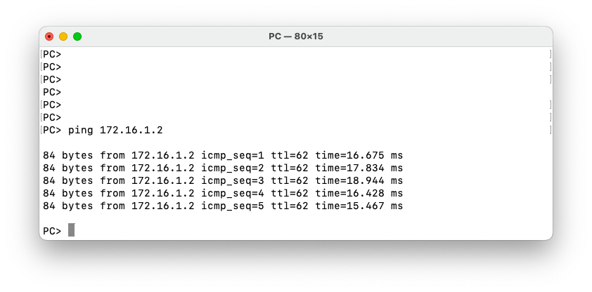
Reachability Test
We will test the ping from the PC to the IP address 172.16.1.2/28 configured on Switch-2.
Let’s also do a traceroute from Switch-2 to PC1.
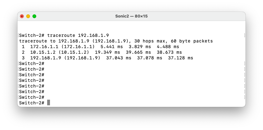
We notice that traffic follows the path Switch-2 – Switch-1 – Switch-4 – PC1.
Failover and Convergence Test
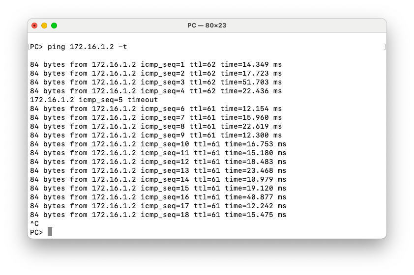
To test the convergence after a link failure, we will launch a continuous ping from the PC to 172.16.1.2 on Switch-2. Then we will disable the link between Switch-1 and Switch-4. Traffic should converge Switch-3.
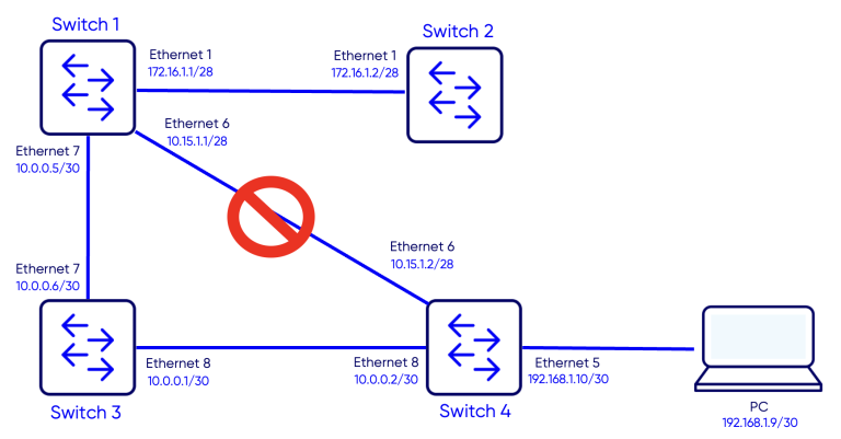
Ping test results
Notice that only one ping times out and then traffic reconverges.
Notes
- Ensure the router ID is explicitly configured and unique across all OSPF routers. If not set manually, OSPF may select an unexpected interface IP, which can cause adjacency issues.
Verify that interfaces participating in OSPF are administratively up and have valid IPv4 addresses configured before enabling OSPF.
When configuring OSPF on VLAN or Port-Channel interfaces, confirm that the underlying member interfaces are operational, otherwise adjacencies will not form.
Use passive interfaces for access-facing or host-facing links to prevent unnecessary OSPF neighbor formation while still advertising the network. For example we can configure interface Ethernet5 on Switch-4 as passive-interface.
If OSPF neighbors do not reach the FULL state, check for mismatched parameters such as area ID, MTU, authentication, or network type.