In this article, we explore how to configure the Virtual Router Redundancy Protocol (VRRP) on Enterprise SONiC. VRRP is a standards-based first-hop redundancy protocol that enables multiple Layer 3 devices to provide a highly available default gateway for end hosts.
The article covers the following topics:
- VRRP overview and operational principles
- Configuring a VRRP group and virtual IP address
- Assigning router priorities
- Enabling and understanding preemption behavior
- Verifying VRRP operation and status
VRRP Overview
VRRP is defined in RFC 5798 and provides default gateway redundancy without requiring any configuration changes on end hosts. Hosts use a virtual IP address (VIP) as their default gateway, which is shared among multiple routers participating in the same VRRP group.
Within a VRRP group:
- One router is elected as the Master and is responsible for forwarding traffic destined to the virtual IP address.
- All other routers operate in the Backup state and monitor the Master’s availability.
- If the Master fails or becomes unreachable, a Backup router automatically transitions to the Master role, ensuring minimal traffic disruption.
The Master router periodically sends VRRP advertisement messages to signal its presence. Backup routers use these advertisements to detect failures and determine when to initiate a takeover. Router selection is primarily based on priority, with the highest priority router becoming the Master. If priorities are equal, the router with the highest interface IP address is elected.
Topology
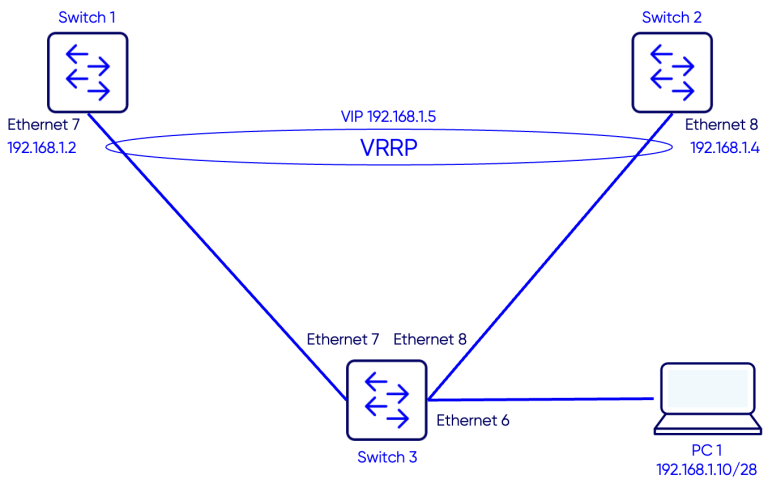
Configuration
Step 1: VRRP Group
Switch 1
Switch-1(config)# interface Ethernet 7
Switch-1(config-if-Ethernet7)# switchport trunk allowed Vlan 10

Switch-1(config)# interface Vlan 10
Switch-1(config-if-Vlan10)# ip address 192.168.1.2/28
Switch-1(config-if-Vlan10)# vrrp 1 address-family ipv4
Switch-1(config-if-Vlan10-vrrp-ipv4-1)# version 2
Switch-1(config-if-Vlan10-vrrp-ipv4-1)# vip 192.168.1.5
Switch-1(config-if-Vlan10-vrrp-ipv4-1)# priority 150
Switch 2
Switch-2(config)# interface Ethernet 8
Switch-2(config-if-Ethernet8)# switchport trunk allowed Vlan add 10

Switch-2(config)# interface Vlan 10
Switch-2(config-if-Vlan10)# ip address 192.168.1.4/28
Switch-2(config-if-Vlan10)# vrrp 1 address-family ipv4
Switch-2(config-if-Vlan10-vrrp-ipv4-1)# vip 192.168.1.5
Step 2: Priority
VRRP uses a priority value to determine which router assumes the Master role within a VRRP group. The priority range is 1 to 254, with higher values indicating a higher preference to become Master. Default priority, if nothing is confiugred, is 100.
The router with the highest configured priority is elected as Master, while the others operate in the Backup state. If priorities are equal, the router with the highest interface IP address is selected. Properly setting priorities ensures deterministic gateway selection and predictable failover behavior in Enterprise SONiC deployments.
In our setup we want Switch-1 to be the master. We will set its priority to 150.
Switch 1
Switch-1(config)# interface Vlan 10
Switch-1(config-if-Vlan10)# vrrp 1 address-family ipv4
Switch-1(config-if-Vlan10-vrrp-ipv4-1)# priority 150
Switch 2
Step 3: Preemption
Preemption is a VRRP feature that allows a router with a higher priority to take over the Master role from a currently active Master. When preemption is enabled, a router that comes online or recovers from a failure will immediately assume the Master role if its priority is higher than the current Master. If preemption is disabled, the current Master retains its role even if a higher-priority router becomes available. Enabling preemption ensures that the router intended to be the primary default gateway actively handles traffic, providing predictable and deterministic failover behavior in Enterprise SONiC networks.
In our setup we want to enable preemption so Switch-1 becomes the master after a failure recovery.
Switch 1
Switch-1(config)# interface Vlan 10
Switch-1(config-if-Vlan10)# vrrp 1 address-family ipv4
Switch-1(config-if-Vlan10-vrrp-ipv4-1)# preempt
Switch 2
Verification
Use the command show vrrp to verify the VRRP status.
Switch 1
Switch-1# show vrrp
          Interface  VRID   State Virtual Address  Cfg_Prio  Curr_Prio   Version     Address
             Vlan10     1  Master     192.168.1.5       150        150         2  192.168.1.2
Switch 2
Switch-2# show vrrp
          Interface  VRID   State Virtual Address  Cfg_Prio  Curr_Prio   Version     Address
             Vlan10     1  Backup     192.168.1.5       100        100         2  192.168.1.4
Testing the VIP reachability
From the PC ping the Virtual IP 192.168.1.5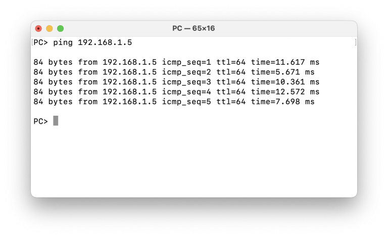
Failover scenario Test
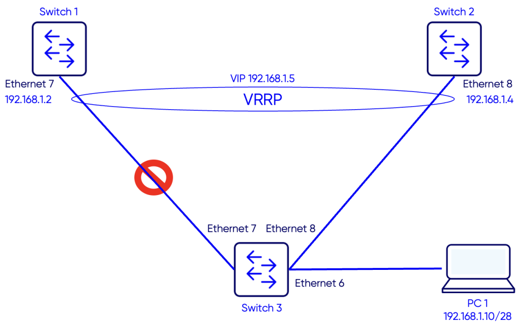
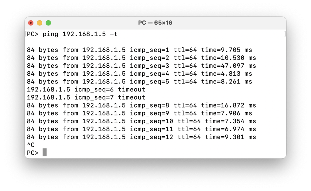
To test VIP reachability in case of the failure of Switch-1 or failure of the link between Switch-1 and Switch-3, we start a continuous ping to the VIP 192.168.1.5 and will simulate breaking the link between Switch-1 and Switch-3.
We notice a couple of ping timeouts and then the responses resume. Once the ping resumes, Switch-2 becomes the Master VRRP router as seen in the outputs below.
Switch 1
Switch-1# show vrrp
          Interface  VRID   State Virtual Address  Cfg_Prio  Curr_Prio   Version     Address
             Vlan10     1    Down     192.168.1.5       150        150         2  192.168.1.2
Switch 2
Switch-2# show vrrp
          Interface  VRID   State Virtual Address  Cfg_Prio  Curr_Prio   Version     Address
             Vlan10     1  Master     192.168.1.5       100        100         2  192.168.1.4
Verifying Preemption
Now we will enable the link between Switch-1 and Switch-3. Switch-1 should become again the Master VRRP router and Switch-2 will be the backup.Switch 1
Switch-1# show vrrp
          Interface  VRID   State Virtual Address  Cfg_Prio  Curr_Prio   Version     Address
             Vlan10     1  Master     192.168.1.5       150        150         2  192.168.1.2
Switch 2
Switch-2# show vrrp
          Interface  VRID   State Virtual Address  Cfg_Prio  Curr_Prio   Version     Address
             Vlan10     1  Backup     192.168.1.5       100        100         2  192.168.1.4