SONiC EVPN-VXLAN Configuration
In this article we will explore how to configure EVPN-VXLAN for a single tenant on Enterprise SONiC. We will cover:
- EVPN-VXLAN architecture overview
- Configuring the underlay network
- Configuring the overlay network
- Configuring VTEP interfaces
- Creating VLANs and mapping them to Layer 2 VNIs
- Verification and troubleshooting
EVPN-VXLAN Overview
EVPN-VXLAN combines EVPN as the control plane with VXLAN for data plane encapsulation. It provides:
- Layer 2 extension across Layer 3 networks
- Multi-tenancy support (VRF optional)
- Simplified host mobility
- Efficient broadcast/multicast handling via VXLAN
In this configuration, we will focus on a single tenant scenario with single Layer 2 VNI (L2VNI), enabling different PCs to communicate across the VXLAN fabric.
Topology
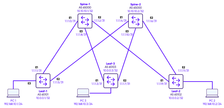
In this design, we deploy a single tenant across a fabric consisting of two spine switches and three leaf switches, using multiple L2VNIs to extend Layer 2 VLANs across the network. Each VLAN is mapped to a unique L2VNI, allowing PCs connected to different leaf switches to communicate seamlessly within the same broadcast domain. BGP EVPN acts as the control plane, advertising MAC addresses and VNI mappings between leaf and spine switches, and enabling dynamic learning and forwarding of Layer 2 traffic. Because this deployment is Layer 2–only, inter-VLAN communication is not possible— all traffic remains within its respective L2VNI. This architecture demonstrates how EVPN-VXLAN can provide scalable Layer 2 connectivity for a single tenant without requiring IP routing.
Configuration
Step 1: Interfaces Configuration
The first step is to configure IP addresses on the Loopbacks and Network-to-Network interfaces between the switches.
Spines configuration
Spine-1
interface Loopback 0
 ip address 10.10.10.1/32
!
interface Ethernet1
 description "Link to Leaf-1"
 no shutdown
 ip address 1.1.1.0/31
!
interface Ethernet2
 description "Link to Leaf-2"
 no shutdown
 ip address 1.1.1.2/31
!
interface Ethernet3
 description "Link to Leaf-3"
 no shutdown
 ip address 1.1.1.8/31
Spine-2
interface Loopback 0
 ip address 10.10.10.2/32
!
interface Ethernet1
 description "Link to Leaf-1"
 no shutdown
 ip address 1.1.1.4/31
!
interface Ethernet2
 description "Link to Leaf-2"
 no shutdown
 ip address 1.1.1.6/31
!
interface Ethernet3
 description "Link to Leaf-3"
 no shutdown
 ip address 1.1.1.10/31
Leaves Configuration
Leaf-1
interface Loopback 0
 ip address 10.0.0.1/32
!
interface Ethernet1
 description "Link to Spine-1"
 no shutdown
 ip address 1.1.1.1/31
interface Ethernet2
 description "Link to Spine-2"
 no shutdown
 ip address 1.1.1.5/31
Leaf-2
interface Loopback 0
 ip address 10.0.0.2/32
!
interface Ethernet1
 description "Link to Spine-1"
 no shutdown
 ip address 1.1.1.3/31
interface Ethernet2
 description "Link to Spine-2"
 no shutdown
 ip address 1.1.1.7/31
Leaf-3
interface Loopback 0
 ip address 10.0.0.3/32
!
interface Ethernet1
 description "Link to Spine-1"
 no shutdown
 ip address 1.1.1.9/31
interface Ethernet2
 description "Link to Spine-2"
 no shutdown
 ip address 1.1.1.11/31
Step 2: Underlay Configuration
In this topology, the spine switches form the backbone, while the leaf switches connect both to the spines and to the tenant devices. eBGP peering is established between each leaf and all spines, creating a full-mesh underlay control plane. This BGP underlay distributes reachability information for all loopback addresses used as VXLAN tunnel endpoints (VTEPs), ensuring that leafs can forward overlay traffic to any other leaf via the spine. By separating the underlay from the overlay, the network provides scalability, redundancy, and predictable forwarding paths, while allowing the overlay (EVPN-VXLAN) to focus purely on tenant L2 connectivity
Spines configuration
Spine-1
router bgp 65000
 router-id 10.10.10.1
!
address-family ipv4 unicast
redistribute connected
 !
 address-family l2vpn evpn
 advertise-all-vni
 !
 neighbor 1.1.1.1
  remote-as 65101
  !
 address-family ipv4 unicast
  activate
  !
  address-family l2vpn evpn
   activate
  !
 neighbor 1.1.1.3
  remote-as 65102
  !
  address-family ipv4 unicast
    activate
  !
  address-family l2vpn evpn
   activate
!
 neighbor 1.1.1.7
  remote-as 65103
  !
address-family ipv4 unicast
  activate
  !
 address-family l2vpn evpn
  activate
Spine-1
router bgp 65000
  router-id 10.10.10.2
!
address-family ipv4 unicast
redistribute connected
 !
 address-family l2vpn evpn
advertise-all-vni
 !
  neighbor 1.1.1.5
  remote-as 65101
  !
address-family ipv4 unicast
  activate
  !
  address-family l2vpn evpn
   activate
  !
 neighbor 1.1.1.11
  remote-as 65102
  !
address-family ipv4 unicast
  activate
  !
 address-family l2vpn evpn
  activate
!
 neighbor 1.1.1.9
  remote-as 65103
  !
address-family ipv4 unicast
  activate
  !
 address-family l2vpn evpn
  activate
Leaves Configuration
Leaf-1
router bgp 65101
 router-id 10.0.0.1
 !
 address-family ipv4 unicast
  redistribute connected
 !
 address-family l2vpn evpn
  advertise-all-vni
 !
 neighbor 1.1.1.0
  remote-as 65000
  !
  address-family ipv4 unicast
   activate
  !
  address-family l2vpn evpn
   activate
!
 neighbor 1.1.1.4
  remote-as 65000
  !
  address-family ipv4 unicast
   activate
  !
  address-family l2vpn evpn
   activate
Leaf-2
router bgp 65102
 router-id 10.0.0.2
 !
 address-family ipv4 unicast
  redistribute connected
 !
 address-family l2vpn evpn
  advertise-all-vni
!
 neighbor 1.1.1.2
  remote-as 65000
  !
  address-family ipv4 unicast
   activate
  !
  address-family l2vpn evpn
   activate
!
 neighbor 1.1.1.10
  remote-as 65000
  !
  address-family ipv4 unicast
   activate
  !
  address-family l2vpn evpn
   activate
Leaf-3
router bgp 65103
 router-id 10.0.0.3
 !
 address-family ipv4 unicast
  redistribute connected
 !
 address-family l2vpn evpn
  advertise-all-vni
!
 neighbor 1.1.1.6
  remote-as 65000
  !
  address-family ipv4 unicast
   activate
  !
  address-family l2vpn evpn
   activate
!
 neighbor 1.1.1.8
  remote-as 65000
  !
  address-family ipv4 unicast
   activate
  !
  address-family l2vpn evpn
   activate
Step 3: Host Connections
The tenant hosts—represented by PCs—are connected directly to the leaf switches. Each host-facing port on the leaf is configured as an access port in VLAN 10, ensuring that traffic from the PC enters the switch untagged and is automatically mapped to the corresponding L2VNI in the VXLAN overlay. This setup allows hosts connected to different leaf switches, but in the same VLAN, to communicate seamlessly across the fabric, while maintaining strict Layer 2 segmentation and traffic isolation between VLANs.
Leaves configuration
Leaf-1
interface Vlan10
 description "Green-Servers VLAN"
!

interface Ethernet3
 no shutdown
 switchport access Vlan 10
Leaf-2
interface Vlan10
 description "Green-Servers VLAN"
!

interface Ethernet3
 no shutdown
 switchport access Vlan 10
Leaf-3
interface Vlan10
 description "Green-Servers VLAN"
!

interface Ethernet3
 no shutdown
 switchport access Vlan 10
Step 4: VTEP Configuration and VLAN-VNI Mapping
The VXLAN Tunnel Endpoint (VTEP) is responsible for encapsulating and decapsulating tenant traffic into VXLAN packets for transport across the underlay fabric. On each leaf switch, a VXLAN interface (for example, vxlan1) is configured with a source IP, typically the loopback address, which serves as the VTEP identifier. Each VLAN in the tenant is then mapped to a unique VXLAN Network Identifier (VNI), allowing the switch to correctly encapsulate traffic for that VLAN. For instance, VLAN 10 can be mapped to VNI 100010, ensuring that all traffic from hosts in VLAN 10 is encapsulated with the correct VXLAN ID when sent across the fabric. This mapping is essential for maintaining Layer 2 isolation and proper overlay forwarding.
Leaves configuration
Leaf-1
interface vxlan vtep1
 source-ip 10.0.0.1
 map vni 100010 vlan 10
Leaf-2
interface vxlan vtep1
 source-ip 10.0.0.2
 map vni 100010 vlan 10
Leaf-3
interface vxlan vtep1
 source-ip 10.0.0.3
 map vni 100010 vlan 10
Verification
BGP Neighbors
In the underlay network, BGP is used to exchange reachability information between spines and leafs. Each spine switch is configured with all leaf switches as BGP neighbors, while each leaf switch is configured with both spines as neighbors. This full-mesh peering ensures that all leafs can reach each other via the spine fabric and that the loopback addresses used as VTEPs are advertised across the underlay. By establishing eBGP sessions in this way, the VXLAN overlay can rely on a robust and fully reachable underlay network for forwarding encapsulated tenant traffic between leafs.
Spine-1
Spine-1# show bgp l2vpn evpn summary
BGP router identifier 10.0.0.1, local AS number 65000 VRF default
Neighbor    V   AS         MsgRcvd   MsgSent   InQ     OutQ    Up/Down         State/PfxRcd
1.1.1.1     4   65101      36        50        0       0       00:18:01        1
1.1.1.3     4   65102      45        49        0       0       00:17:33        1
1.1.1.7     4   65103      36        49        0       0       00:17:14        2

Total number of neighbors 3
Total number of neighbors established 3
Spine-2
Spine-2# show bgp l2vpn evpn summary
BGP router identifier 10.0.0.2, local AS number 65000 VRF default
Neighbor     V   AS         MsgRcvd   MsgSent   InQ     OutQ    Up/Down         State/PfxRcd
1.1.1.5      4   65101      46        52        0       0       00:00:06        1
1.1.1.9      4   65103      39        51        0       0       00:20:06        1
1.1.1.11     4   65102      48        51        0       0       00:20:24        1

Total number of neighbors 3
Total number of neighbors established 3
Leaf-1
Leaf-1# show bgp l2vpn evpn summary
BGP router identifier 10.0.0.1, local AS number 65101 VRF default
Neighbor    V   AS         MsgRcvd   MsgSent   InQ     OutQ    Up/Down         State/PfxRcd
1.1.1.0     4   65000      55        46        0       0       00:21:51        0
1.1.1.4     4   65000      54        53        0       0       00:01:03        0

Total number of neighbors 2
Total number of neighbors established 2
Leaf-2
Leaf-2# show bgp l2vpn evpn summary
BGP router identifier 10.0.0.2, local AS number 65102 VRF default
Neighbor     V   AS         MsgRcvd   MsgSent   InQ     OutQ    Up/Down         State/PfxRcd
1.1.1.2      4   65000      55        52        0       0       00:21:53        0
1.1.1.10     4   65000      53        52        0       0       00:21:51        0

Total number of neighbors 2
Total number of neighbors established 2
Leaf-3
Leaf-3# show bgp l2vpn evpn summary
BGP router identifier 10.0.0.3, local AS number 65103 VRF default
Neighbor    V   AS         MsgRcvd   MsgSent   InQ     OutQ    Up/Down         State/PfxRcd
1.1.1.6     4   65000      23        19        0       0       00:03:40        0
1.1.1.8     4   65000      23        19        0       0       00:03:44        0

Total number of neighbors 2
Total number of neighbors established 2
VXLAN Tunnels
Once the VTEP and VLAN VNI mappings are configured, it is important to verify that the VXLAN tunnels are operational. Using the command show vxlan tunnel, you can check the status of each VXLAN interface, confirm the source and destination VTEPs, and ensure that the tunnels are up. A healthy VXLAN tunnel indicates that the leaf switches can successfully encapsulate and decapsulate tenant traffic, enabling communication between hosts across the fabric. This verification step helps confirm that the overlay network is correctly built on top of the BGP underlay and that the L2VNIs are properly mapped.
Leaf-1
Leaf-1# show vxlan tunnel

        Name                SIP                DIP           source    Group     D-VNI     operstatus
        ====                ===                ===           ======    =====     =====     ==========
   EVPN_10.0.0.2          10.0.0.1           10.0.0.2         EVPN    internal     no       oper_up
   EVPN_10.0.0.3          10.0.0.1           10.0.0.3         EVPN    internal     no       oper_up
Leaf-2
Leaf-2# show vxlan tunnel
Name SIP DIP source Group D-VNI operstatus
==== === === ====== ===== ===== ==========
EVPN_10.0.0.1 10.0.0.2 10.0.0.1 EVPN internal no oper_up
EVPN_10.0.0.3 10.0.0.2 10.0.0.3 EVPN internal no oper_up
BGP routes
The command show bgp l2vpn evpn route
displays the EVPN routing information learned and advertised by the switch through BGP. It shows all EVPN route types—including MAC/IP advertisements, inclusive multicast routes, and Ethernet segment information—along with their associated VNIs, next hops, and originating peers. This output allows you to verify that MAC addresses and VNI mappings are being correctly exchanged between leaf switches and that the control plane is functioning as expected. It is one of the primary commands for confirming that the EVPN overlay has been successfully established.
Leaf-1
Leaf-1# show bgp l2vpn evpn route
BGP table version is 6, local router ID is 10.0.0.1
Status codes: s suppressed, d damped, h history, * valid, > best, i - internal, q queued, r RIB-failure
Origin codes: i - IGP, e - EGP, ? - incomplete
EVPN type-1 prefix: [1]:[EthTag]:[ESI]:[IPlen]:[VTEP-IP]:[Frag-id]
EVPN type-2 prefix: [2]:[EthTag]:[MAClen]:[MAC]:[IPlen]:[IP]
EVPN type-3 prefix: [3]:[EthTag]:[IPlen]:[OrigIP]
EVPN type-4 prefix: [4]:[ESI]:[IPlen]:[OrigIP]
EVPN type-5 prefix: [5]:[EthTag]:[IPlen]:[IP]
   Network          Next Hop            Metric LocPrf Weight Path
                    Extended Community
Route Distinguisher: 10.0.0.1:10
*>   [2]:[0]:[48]:[00:50:79:66:68:01]
                    10.0.0.1                                  32768 i
                    ET:8 RT:65101:100010
*>   [3]:[0]:[32]:[10.0.0.1]
                    10.0.0.1                                  32768 i
                    ET:8 RT:65101:100010
Route Distinguisher: 10.0.0.1:20
*>   [3]:[0]:[32]:[10.0.0.1]
                    10.0.0.1                                  32768 i
                    ET:8 RT:65101:100020
Route Distinguisher: 10.0.0.1:100
*>   [3]:[0]:[32]:[10.0.0.1]
                    10.0.0.1                                  32768 i
                    ET:8 RT:65101:100100
Route Distinguisher: 10.0.0.1:200
*>   [3]:[0]:[32]:[10.0.0.1]
                    10.0.0.1                                  32768 i
                    ET:8 RT:65101:100200
Route Distinguisher: 10.0.0.2:10
*    [3]:[0]:[32]:[10.0.0.2]
                    10.0.0.2                                      0 65000 65102 i
                    RT:65102:100010 ET:8
*>   [3]:[0]:[32]:[10.0.0.2]
                    10.0.0.2                                      0 65000 65102 i
                    RT:65102:100010 ET:8
Route Distinguisher: 10.0.0.2:20
*    [3]:[0]:[32]:[10.0.0.2]
                    10.0.0.2                                      0 65000 65102 i
                    RT:65102:100020 ET:8
*>   [3]:[0]:[32]:[10.0.0.2]
                    10.0.0.2                                      0 65000 65102 i
                    RT:65102:100020 ET:8
Route Distinguisher: 10.0.0.2:100
*    [3]:[0]:[32]:[10.0.0.2]
                    10.0.0.2                                      0 65000 65102 i
                    RT:65102:100100 ET:8
*>   [3]:[0]:[32]:[10.0.0.2]
                    10.0.0.2                                      0 65000 65102 i
                    RT:65102:100100 ET:8
Route Distinguisher: 10.0.0.2:200
*    [3]:[0]:[32]:[10.0.0.2]
                    10.0.0.2                                      0 65000 65102 i
                    RT:65102:100200 ET:8
*>   [3]:[0]:[32]:[10.0.0.2]
                    10.0.0.2                                      0 65000 65102 i
                    RT:65102:100200 ET:8
Route Distinguisher: 10.0.0.3:10
*    [2]:[0]:[48]:[00:50:79:66:68:06]
                    10.0.0.3                                      0 65000 65103 i
                    RT:65103:100010 ET:8
*>   [2]:[0]:[48]:[00:50:79:66:68:06]
                    10.0.0.3                                      0 65000 65103 i
                    RT:65103:100010 ET:8
*    [3]:[0]:[32]:[10.0.0.3]
                    10.0.0.3                                      0 65000 65103 i
                    RT:65103:100010 ET:8
*>   [3]:[0]:[32]:[10.0.0.3]
                    10.0.0.3                                      0 65000 65103 i
                    RT:65103:100010 ET:8
Displayed 11 prefixes (17 paths)
In our test, we perform a ping between two PCs in the same VLAN with the following MAC addresses:
PC-1: 00:00:50:79:66:68:01 (connected to Leaf-1)
PC-3: 00:00:50:79:66:68:06 (connected to Leaf-3)
Route Distinguisher: 10.0.0.1:10
*> [2]:[0]:[48]:[00:50:79:66:68:01]
                    10.0.0.1
                    ET:8 RT:65101:100010
This entry represents the local MAC address 00:50:79:66:68:01, learned directly on Leaf-1. The next hop is 10.0.0.1, which is the VTEP address of Leaf-1 itself, confirming that this MAC is locally attached.
Further down in the table we see:
Route Distinguisher: 10.0.0.3:10
*> [2]:[0]:[48]:[00:50:79:66:68:06]
                    10.0.0.3
                    RT:65103:100010 ET:8
This Type-2 route shows that MAC address 00:50:79:66:68:06 has been learned from a remote leaf switch with VTEP IP 10.0.0.3 (Leaf-3). The presence of this route confirms that Leaf-1 has successfully received the MAC advertisement for PC-B via BGP EVPN.
MAC Addresses
We use the command show mac address-table to verify mac addresses.
Leaf-1
Leaf-1# show mac address-table
-----------------------------------------------------------
VLAN         MAC-ADDRESS         TYPE         INTERFACE
-----------------------------------------------------------
10          00:50:79:66:68:06   DYNAMIC       VxLAN DIP: 10.0.0.3
10          00:50:79:66:68:01   DYNAMIC       Ethernet3
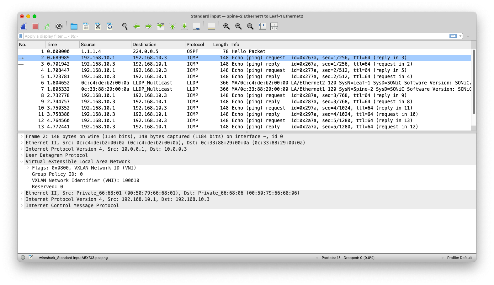
Test
Ping from PC1 to PC3
Let’s now test a ping from PC1 to PC1.
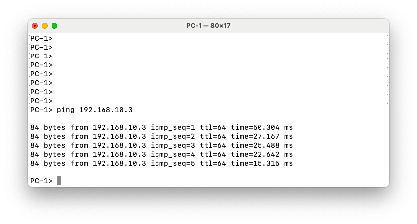
The ping between the two PCs is successful, confirming end-to-end Layer 2 connectivity across the VXLAN fabric. The Wireshark capture on the link between Spine-1 and Leaf-3 shows the ICMP packets encapsulated within UDP, as expected for VXLAN transport. The capture also clearly displays the VXLAN header, including VNI 100010, which corresponds to the L2VNI configured for this VLAN in our overlay. This confirms that the traffic is properly encapsulated, routed through the spine, and decapsulated at the remote leaf, allowing communication between hosts in the same VLAN across different leaf switches.