SONiC MCLAG Configuration
In this article we will explore how to configure Multi-Chassis Link Aggregation (MCLAG) on Enterprise SONiC. We will cover:
- MCLAG overview
- Configuring the peer link
- Configuring the keepalive link
- Configuring PortChannel interfaces as MCLAG
- Verifying the configuration
MCLAG Overview
Multi-Chassis Link Aggregation (MCLAG) provides link redundancy and load balancing by connecting a downstream device (for example, a server or a switch) to two upstream SONiC switches using PortChannels. Both switches appear as a single logical device to the downstream device.
Key components of MCLAG:
- Peer link — Connects the two MCLAG peers to synchronize state. Layer 2 link connects MCLAG peer switches and acts as data backup path between MCLAG peers.
- Keepalive link — Used to detect peer failure and avoid split-brain. Layer 3 link that connects MCLAG peer switches. It carries periodic heartbeat messages between MCLAG peers
- MCLAG PortChannel — Aggregates interfaces from both peers to downstream devices.
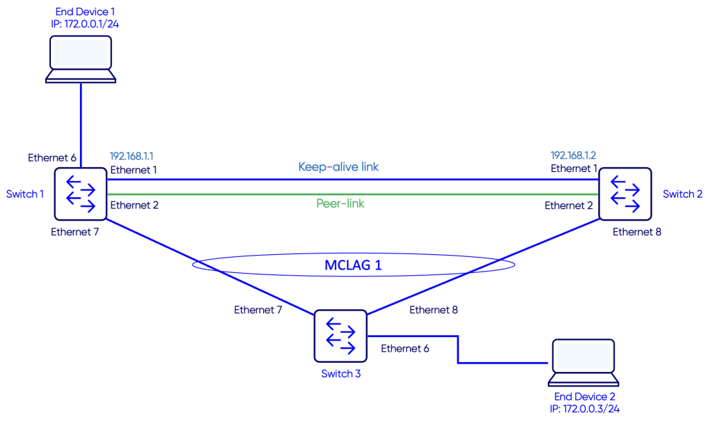
Topology
Configuration
Step 1: Peer-Link
The link Switch-1 (Ethernet 2) to Switch-2 (Ethernet 2) will be configured as the peer-link. The role of the peer-link is to connect the two MCLAG peers to synchronize their states. It is a layer 2 link that connects the two MCLAG peer switches. This link also acts as data backup path between MCLAG peers.
Step 2: Keep-alive link
In an MCLAG setup, the keepalive link serves as a dedicated heartbeat between the two MCLAG peers, ensuring that each switch can quickly detect whether the other is alive.
Unlike the peer-link, which carries control traffic, MAC synchronization, and sometimes forwards traffic for remote MACs, the keepalive link is lightweight and carries only liveness information.
Its primary purpose is to prevent split-brain scenarios by providing an independent check of peer availability. The link can be a simple Layer 3 connection over the management network or a direct Layer 2 link, and it typically does not require a dedicated VLAN.
In our example, we will use the link Switch-1 (Ethernet 1) to Switch-2 (Ethernet 1) as the keep-alive link.
We will configure IP address 192.168.1.1/24 on Switch-1 and 192.168.1.2/24 on Switch-2.
Switch 1
Switch-1# configure terminal
Switch-1(config)# interface Ethernet 1
Switch-1(config-if-Ethernet1)# no shutdown
Switch-1(config-if-Ethernet1)# ip address 192.168.1.1/30
Switch-1(config-if-Ethernet1)# end
Switch 2
Switch-2# configure terminal
Switch-2(config)# interface Ethernet 1
Switch-2(config-if-Ethernet1)# no shutdown
Switch-2(config-if-Ethernet1)# ip address 192.168.1.2/30
Switch-2(config-if-Ethernet1)# end
Step 3: Configuring the MCLAG domain
In this MCLAG configuration on Switch-1, we’re setting up domain 1 to enable link aggregation across two switches. We assign a local source IP (192.168.1.1) and the peer’s IP (192.168.1.2) for the keepalive link, which acts as a heartbeat to monitor the peer’s availability and prevent split-brain scenarios. The peer-link is configured on Ethernet2, providing a dedicated channel to synchronize MAC addresses and MCLAG state between the two switches.
We explicitly define the MCLAG system MAC (00:00:00:00:00:11), which is the MAC address that downstream devices will see for all traffic coming from the MCLAG. This system MAC should match on both MCLAG peers to ensure that the dual-homed links appear as a single logical device to connected devices, preventing forwarding loops and MAC flaps.
The configuration also includes a keepalive interval of 1 second, ensuring rapid detection of peer failures, and a session timeout of 30 seconds to control how long a peer can be unreachable before member ports are affected. Additionally, the delay-restore of 300 seconds prevents flapping by delaying the restoration of member ports after a peer comes back online. A backup keepalive interval of 30 seconds provides a secondary mechanism to check peer availability if the primary link fails. Altogether, this configuration ensures fast failover, synchronized forwarding state, and a stable, loop-free network for dual-homed connections.
Switch 1
Switch-1# configure terminal
Switch-1(config)# mclag domain 1
Switch-1(config-mclag-domain-1)# source-ip 192.168.1.1
Switch-1(config-mclag-domain-1)# peer-ip 192.168.1.2
Switch-1(config-mclag-domain-1)# peer-link Ethernet2
Switch-1(config-mclag-domain-1)# mclag-system-mac 00:00:00:00:00:11
Switch-1(config-mclag-domain-1)# keepalive-interval 1
Switch-1(config-mclag-domain-1)# session-timeout 30
Switch-1(config-mclag-domain-1)# delay-restore 300
Switch-1(config-mclag-domain-1)# backup-keepalive interval 30
Switch 2
Switch-2# configure terminal
Switch-2(config)# mclag domain 1
Switch-2(config-mclag-domain-1)# source-ip 192.168.1.2
Switch-2(config-mclag-domain-1)# peer-ip 192.168.1.1
Switch-2(config-mclag-domain-1)# peer-link Ethernet2
Switch-2(config-mclag-domain-1)# mclag-system-mac 00:00:00:00:00:11
Switch-2(config-mclag-domain-1)# keepalive-interval 1
Switch-2(config-mclag-domain-1)# session-timeout 30
Switch-2(config-mclag-domain-1)# delay-restore 300
Switch-2(config-mclag-domain-1)# backup-keepalive interval 30
Step 4: Configuring MCLAG PortChannels
On both switches, configure a Port-Channel that connects to the downstream device (switch 3) and make it an MCLAG
Switch 1
Switch-1# configure terminal
Switch-1(config)# interface PortChannel10
Switch-1(conf-if)# switchport trunk allowed Vlan 10
Switch-1(conf-if)# no shutdown
Switch-1(conf-if)# mclag 1
Switch-1(conf-if)# exit
Switch-1(config)#
Switch-1(config)# interface Ethernet7
Switch-1(conf-if)# channel-group 10
Switch 2
Switch-2# configure terminal
Switch-2(config)# interface PortChannel10
Switch-2(conf-if)# switchport trunk allowed Vlan 10
Switch-2(conf-if)# no shutdown
Switch-2(conf-if)# mclag 1
Switch-2(conf-if)# exit
Switch-2(config)#
Switch-2(config)# interface Ethernet8
Switch-2(conf-if)# channel-group 10
Now the MCLAG should be configured and operational.
Verification
Use the command show mclag brief to verify the MCLAG status
Switch 1
Switch-1# show mclag brief

Domain ID            : 1
Role                 : active
Session Status       : up
Peer Link Status     : up
Source Address       : 192.168.1.1
Peer Address         : 192.168.1.2
Session Vrf          : default
Peer Link            : Ethernet2
Keepalive Interval   : 1 secs
Session Timeout      : 30 secs
Delay Restore        : 300 secs
System Mac           : 0c:01:f8:56:00:0a
Mclag System Mac     : 00:00:00:00:00:11


Backup Keepalive Session Information:
-----------------------------------
Session Vrf          : default
Session Status       : down
Source Address       :
Peer Address         :
Keepalive Interval   : 30 secs
-----------------------------------


Number of MLAG Interfaces:1
-----------------------------------------------------------
MLAG Interface       Local/Remote Status
-----------------------------------------------------------
PortChannel10            up/up
Switch 2
Switch-2# show mclag brief

Domain ID            : 1
Role                 : standby
Session Status       : up
Peer Link Status     : up
Source Address       : 192.168.1.2
Peer Address         : 192.168.1.1
Session Vrf          : default
Peer Link            : Ethernet2
Keepalive Interval   : 1 secs
Session Timeout      : 30 secs
Delay Restore        : 300 secs
System Mac           : 0c:01:f8:56:00:0a
Mclag System Mac     : 00:00:00:00:00:11


Backup Keepalive Session Information:
-----------------------------------
Session Vrf          : default
Session Status       : down
Source Address       :
Peer Address         :
Keepalive Interval   : 30 secs
-----------------------------------


Number of MLAG Interfaces:1
-----------------------------------------------------------
MLAG Interface       Local/Remote Status
-----------------------------------------------------------
PortChannel10            up/up
The show mclag briefcommand gives a quick overview of the MCLAG domain and its health. In this output, domain 1 has Switch-1 as the active peer, and the session status is up, which means the two MCLAG peers are successfully communicating. You should check that the peer-link (Ethernet2) is also up, as this ensures MAC and state synchronization between the switches is working correctly.
The source and peer IP addresses show the keepalive link endpoints, with a keepalive interval of 1 second and a session timeout of 30 seconds, which allows rapid detection if the peer becomes unreachable. The delay restore of 300 seconds prevents flapping by delaying the restoration of member ports after a peer comes back online.
The system MAC addresses are important: the System Mac is the local MAC of this switch, while the Mclag System Mac (00:00:00:00:00:11) is the shared MAC that both peers advertise to downstream devices. You should make sure this MCLAG system MAC matches on both peers, so the dual-homed links appear as a single logical device and avoid loops or MAC flaps.
Finally, the MLAG interface table shows the member PortChannel(s). Here, PortChannel10 is up/up for both local and remote status, meaning traffic can flow normally and redundancy is active. You should always check that the session is up, the peer-link is up, and all member interfaces are up/up to confirm that the MCLAG is healthy and fully operational.
Use the command show mac address-table to verify learned MAC addresses
Switch 1
Switch-1# show mac address-table
-----------------------------------------------------------
VLAN         MAC-ADDRESS         TYPE         INTERFACE
-----------------------------------------------------------
1           0c:55:56:3c:00:08   DYNAMIC       PortChannel10
1           0e:55:56:3c:00:0a   DYNAMIC       PortChannel10
10          00:50:79:66:68:00   DYNAMIC       Ethernet6
10          00:50:79:66:68:01   DYNAMIC       PortChannel10
Switch 2
Switch-2# show mac address-table
-----------------------------------------------------------
VLAN         MAC-ADDRESS         TYPE         INTERFACE
-----------------------------------------------------------
1           0c:5d:13:0e:00:09   DYNAMIC       PortChannel10
1           0c:55:56:3c:00:0a   DYNAMIC       PortChannel10
1           0e:55:56:3c:00:0a   DYNAMIC       PortChannel10
10          00:50:79:66:68:00   DYNAMIC       Ethernet2
10          00:50:79:66:68:01   DYNAMIC       PortChannel10
On switch-1 we can see the MAC address of PC2 00:50:79:66:68:01learned on PortChannel10 and PC1 00:50:79:66:68:00learned on Ethernet6.
Testing Failover Scenario
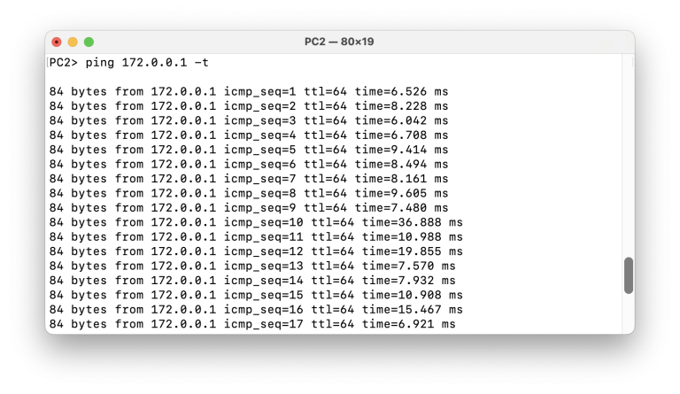
To test the failover, let’s start a continuous ping from PC2 to PC1.
Then we will disable the link between Switch-1 and Switch-2 and observe the state of the traffic.
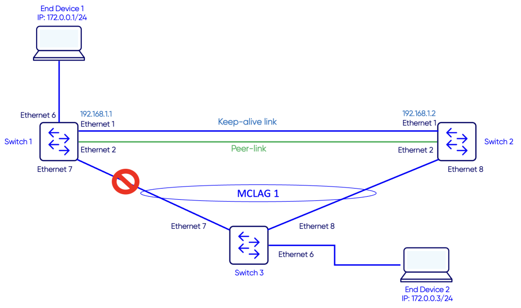
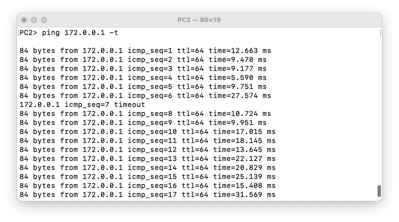
We see that one ping timed out and then traffic reconverges from the alternative path from Switch-3 to Switch-2.
Notes
- Always make sure the MCLAG system MAC matches on both peers, so dual-homed links appear as a single logical device and avoid loops or MAC flaps.
- The peer-link must be up and properly configured, as it carries MCLAG state and MAC synchronization between peers.
- Check the keepalive link and session status to ensure rapid failure detection and prevent split-brain scenarios.
- Confirm that all member PortChannels are up/up for both local and remote status, ensuring traffic can flow normally and redundancy is active.